7.7 ACS Apertures
As discussed in Section 3.3, the ACS consists of three cameras: the WFC, the HRC, and the SBC. The WFC is constructed of two CCDs each nominally 2048 by 4096 pixels, with their long sides adjacent to form a roughly square array, 4096 pixels on a side. The HRC CCD and the SBC MAMA detectors are each 1024 pixels square.
7.7.1 WFC Apertures
The active image area of each WFC detector is 4096 by 2048 pixels. The mean scale is 0.049 arcseconds/pixel, and the combined detectors cover an approximately square area of 202 arcseconds on a side. In establishing reference pixel positions we have to consider the overscan pixel areas which extend 24 pixels beyond the edges in the long direction. So each CCD must be regarded as a 4144 by 2048 pixel area. The gap between the two CCDs is equivalent to 50 pixels. In Figure 7.3 the letters A, B, C, and D show the corner locations of the four readout amps.
We define apertures named WFC1 and WFC2 which represent the two CCDs, with their reference points near the geometric center of each chip. The positions have been moved about 50 pixels from the center line to avoid a discontinuity at the amplifier readout boundary. However, we keep two other apertures named WFC1-FIX and WFC2-FIX at the original central locations (2072,1024). For extended sources, choosing new positions may not be of any advantage and it may be more effective to use these fixed positions.
The aperture WFC encompasses both detectors, and has its reference point near the overall center but about 10 arcseconds away from the interchip gap. This has been chosen to be position (2124,200) on the WFC1 CCD. Again, this has been moved away from the center line, but the reference point for WFC-FIX remains at (2073,200). Selection of WFC1, WFC2 or WFC only changes the pixel where the target will be positioned. In all three cases data is normally delivered in a file containing two imsets, one for each detector. See the ACS Data Handbook for details of the ACS data format. Reading out a subarray, which consists of part of only one of the chips, is done only if requested.
Figure 7.3: WFC aperture definitions.WFCENTER is similar to WFC, but is placed at the center of the combined WFC full field. The center is defined as the average of the four corners in the distortion corrected space. Because of the scale variation this does not appear at the center in pixel space, but rather is on WFC2 about 20 pixels from the edge. Selection of WFCENTER can be of use in obtaining observations with maximum overlap at unique orientations and for mosaics.
For sets of observations which take place over a substantial part of a year, the telescope roll limitations will require measurements to be taken over most of the angular range. On sky, the WFC aperture is roughly square, and it is natural to design observations in steps of 90× to consistently cover the same area. There will be some region at the edges not covered at all four orientations. However, a square area of side 194.8 arcseconds centered on WFCENTER, and with edges parallel to the V2 and V3 axes, is overlapped at all four positions. In designing a mosaic which combines observations at 90× steps, a translation of about 190 arcseconds between pointings would provide continuous coverage.
7.7.2 Ramp Filter Apertures
WFC Ramp Filter Apertures
There are five ramp filters. Each ramp filter consists of three segments (inner, middle, outer) that can be rotated across the WFC field of view as indicated in Figure 7.4. The IRAMP filters can only be placed on WFC1 in a location which will define the aperture WFC1-IRAMP and the ORAMP filters only on WFC2 creating the aperture WFC2-ORAMP. The MRAMP filters can lie on WFC1 or WFC2 with corresponding apertures WFC1-MRAMP and WFC2-MRAMP. The approximate aperture locations are indicated in Figure 7.4, while actual data obtained during ground calibrations are overlayed on an image of a ramp filter in Figure 7.5. Operationally, a fixed reference point will be defined for each detector and filter combination. Then the ramp filter will be rotated to place the required wavelength at the reference position.
Figure 7.4: Schematic WFC apertures and ramp filters.Shown are the approximate active areas defined by the filters. The actual readout areas are the quadrants for the polarizers and small (HRC) filters, and either the quadrant or the full chip for the ramp filters.
The reference positions for all defined apertures are given in Table 7.7 in pixels, and in the telescope V2,V3 reference frame where values are measured in arcseconds. The values given here are based on in-flight calibration results. The x and y axis angles are measured in degrees from the V3 axis towards the V2 axis. This is in the same sense as measuring from North to East on the sky. The “extent” of the ramp filter apertures given in Table 7.7 are the FWHM of the monochromatic patches (visible in Figure 7.4) measured from a small sample of ground calibration data. To use a ramp filter in a Phase II program, specify the filter name, the central wavelength, and the aperture. The scheduling software will then automatically rotate the filter to the appropriate wavelength, and point at the reference point of the aperture chosen.
The aperture chosen may either be the full chip or just the quadrant on which the ramp filter lies. This second choice was new as of Cycle 15, and requires that the aperture be specified. The apertures matching each filter are given in Table 7.7. Those with names ending in Q are the quadrants. It will normally be preferable to choose the quadrant aperture to save data volume and buffer dumping time. All listed apertures will be supported and may also be used with non-ramp filters. A target may thereby be put at the same position using a ramp and a non-ramp filter.Figure 7.5: Monochromatic patches in ground calibration data showing actual aperture sizes through ramp filters (superimposed on photo of ramp filters).HRC Ramp Filter Apertures
Only the middle segments of the five ramp filters can be used with the HRC. They are FR914M, FR459M, FR505N, FR388N and FR656N. All five middle segments can be used with any of the HRC apertures listed in Table 7.8 (see Table 7.9 for the aperture reference positions). There are no special ramp apertures with the HRC because when a ramp filter is used with the HRC it covers the entire region over the HRC chip. This region is defined by the HRC aperture in Table 7.9. To use the HRC-512 or HRC-SUB1.8 subarray apertures with a ramp filter, POS TARGs will have to be used to align the aperture correctly.
As with the WFC, to use a ramp filter specify the filter name, the wavelength and the aperture in the Phase II proposal. The fixed reference point is defined operationally depending on the detector, aperture and filter combination. Please refer to Section 7.3.1, Section 5.3.1, and ACS ISR 02-01 for further information.
7.7.3 The Small Filter Apertures
When a filter designed for the HRC is used with the WFC, it only covers a small area on either WFC1 or WFC2. The projected filter position may be placed on either chip by selection of the filter wheel setting. Figure 7.4 shows how the filter projection may be placed so as to avoid the borders of the chips. When a WFC observation is proposed using a HRC filter spacecraft commanding software automatically uses internal built-in apertures designed for these observing scenarios, called WFC1-SMFL and WFC2-SMFL. Reference positions at or near the center of these apertures are defined so that a target may be placed in the region covered by the chosen filter.
The axis angles given in Table 7.7 do not refer to the edges of the apertures as drawn, but rather to the orientation of the x and y axes at the WFC reference pixel. These angles vary slightly with position due to geometric distortion.
For the polarizers and F892N used with WFC, the default will be to read out a subarray. The subarray will be a rectangular area with sides parallel to the detector edges which encompasses the indicated filtered areas. For ramp filters the default will be to readout the entire WFC detector, unless a polarizer is used with the ramp filter, in which case a subarray is readout. Users cannot override the small filter subarrays.
(arcsec)
pixel
V2,V3
(arcsec)
on WFC1
on WFC2
1Apertures are automatically created by commanding software when a HRC filter is used in WFC observations. (Apertures are not listed in the APT aperture pull-down menu.)
2Apertures are automatically created by commanding software when a polarizer filter is used. Same parameters apply for POL60 and POL120 in V and UV. (Apertures are not listed in the APT aperture pull-down menu.)
23. Extent (arcsec) is the smaller of actual pixel domain readout and the area actively exposed to sky. For RAMP associated apertures the leading dimension is size yielding coverage at the specified wavelength.
Table 7.8: Ramp filter apertures.7.7.4 Polarizer Apertures
Apertures have been provided for use with the polarizer sets similar to the SMFL apertures. These apertures are selected automatically when a polarizing spectral element is used, and a single WFC chip quadrant readout is obtained. The aperture parameters given in Table 7.7 are valid for all three polarizing filters in each polarizer set, UV or visible, to the stated significant figures.
7.7.5 HRC Apertures
The HRC has an area of 1062 by 1024 including 19 physical overscan pixels at each end in the x direction. The active area is 1024 by 1024 pixels. The mean scales along the x and y directions are 0.028 and 0.025 arcseconds/pixel, thus providing a field of view of about 29 by 26 arcseconds in extent. The anisotropy and variation of scales is discussed in Section 10.3 of this handbook. The reference point for the aperture labelled HRC-FIX, and initially for HRC, is at the geometric center, (531,512). As with the WFC apertures, there may be reason to move the HRC reference point later.
The HRC is equipped with two coronagraphic spots, nominally 1.8 and 3.0 arcseconds in diameter and a coronagraphic finger, 0.8 arcseconds in width. Apertures HRC-CORON1.8, HRC-CORON3.0, and HRC-OCCULT0.8 are defined to correspond to these features. The coronagraphic spots are only in the optical train and thus in the data if HRC-CORON1.8 or HRC-CORON 3.0 are specified. Their positions are shown in Figure 7.6 (left panel). In addition we define a target acquisition aperture, HRC-ACQ designed for acquiring targets which are subsequently automatically placed behind a coronagraphic spot or the occultation finger. The positions of the coronagraphic spots have been found to fluctuate. Observations will need to incorporate a USE OFFSET special requirement to allow current values to be inserted at the time of the observation (see the Phase II Proposal Instructions).
A substantial region masked out by the occulting finger will be present in the HRC data (Figure 7.6 -- right panel). The occulting finger is not retractable -- it will be in every HRC exposure. However as with any other detector feature or artifact, the "lost" data can be recovered by combining exposures which were suitably shifted with respect to each other. A dither pattern, ACS-HRC-DITHER-LINE has been defined for this purpose and spans the area flagged for the HRC occulting finger (~1.6 arcseconds or ~56 pixels wide), with an extra ~0.3 arcseconds or ~10 pixels of overlap. More details can be found in the Phase II Proposal Instructions.
Use of the prism PR200L requires specifying aperture HRC, but results in a reference point of [671,512] to optimally center the target coordinates within the somewhat vignetted prism field of view. Although the HRC direct imaging and PR200L prism apertures have the same name in APT, they are actually distinct, and HST executes a small angle maneuver between observations of a given target with them, to compensate for the positional deflection by the prism. One consequence is that the Special Requirement SAME POS AS cannot be used among mixed direct and prism exposures, as always with different apertures.
Figure 7.6: HRC coronagraphic finger and spots (left), coronagraphic finger always in data (right)Table 7.9: HRC aperture parameters.
1These values fluctuate and will be updated at the time of the observation.
2HRC-PRISM is automatically created by commanding software when spectral element PR200L and aperture HRC are selected in APT.
7.7.6 SBC Apertures
The SBC aperture is 1024 pixels square. There are no overscan pixels to consider. The x and y scales are 0.034 and 0.030 arcseconds/pixel leading to a coverage on the sky of 35 by 31 arcseconds. The reference point has been moved to (512,400) to place targets further from a bad anode which disables several rows of the detector near y = 600. As with the CCDs we maintain an SBC-FIX aperture which will always have position (512,512). MAMA detectors slowly lose efficiency with each exposure, therefore the SBC reference point may be shifted again if the chosen position shows this effect to a measurable degree.
The (512,512) reference point falls near to the same position in (V2,V3) as the HRC, namely (205, 470), and the x and y axis angles are -85.4× and -0.9×.
Use of either prism PR110L or PR130L requires use of aperture SBC and results in a reference point of [425,400] to optimally center the target coordinates with respect to vignetting on the right side of the field and to avoid a set of bad rows at 599 to 605.
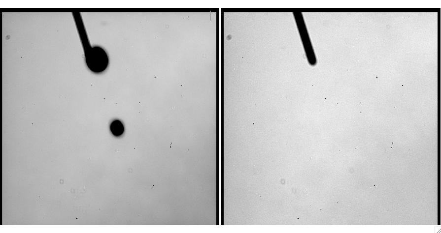
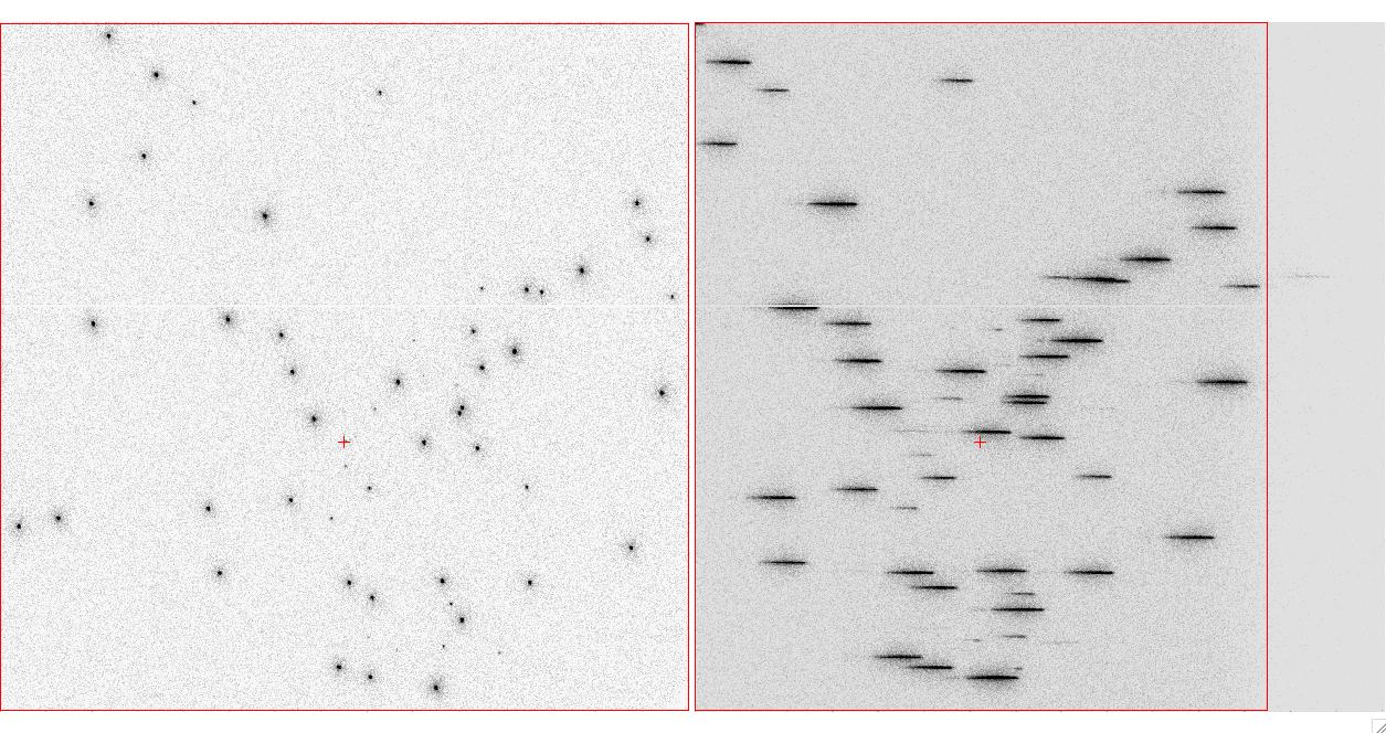
Although the SBC direct imaging and prism apertures have the same name in APT, they are actually distinct, and HST executes a small angle maneuver between observations of a given target with them, to compensate for the positional deflection by the prisms. One consequence is that the Special Requirement SAME POS AS cannot be used among mixed direct and prism exposures. Figure 7.7 shows a direct and prism observation of the same field. The prism now is vignetted on the positive x side. The reference points and the small angle maneuver place the same target near the reference point of each view.
Figure 7.7: Direct and prism observations of NGC6681.Direct and prism observations of NGC6681. The reference point is defined to be at the center of each aperture in the x direction but below the center in the y direction to avoid the bad rows.
Table 7.10: SBC aperture parameters
Name
1SBC-PRISM is automatically created by commanding software when spectral elements PR110L and PR130L, and aperture SBC, are selected in APT.
|
Space telescope Science Institute http://www.stsci.edu |