10.3 Distortion in the ACS
The ACS detectors exhibit more distortion than previous HST instruments. The principal reason for this is that the optics have been designed with a minimum number of components, consistent with correcting for the spherical aberration induced by the OTA, without introducing coma. The result is a high throughput, but focal surfaces far from normal to the principal rays. The WFC detector is tilted at 22 deg giving an elongation of 8% while the HRC and SBC have a 25× tilt leading to an elongation of 12%. In each case, the scales in arcseconds per pixel are smaller along the radial direction of the OTA (Optical Telescope Assembly) field of view than along the tangential direction.
The orientations of the ACS detector edges are approximately in line with the V2 and V3 coordinate axes of the telescope. Consequently, the eigenaxes of the scale transformation are along the diagonals for WFC, and the apertures and pixels appear non-rectangular in the sky projection. For the HRC and SBC the situation is even more irregular because the aperture diagonals do not lie along a radius of the HST field of view. Figure 7.8 shows the ACS apertures in the telescope’s V2V3 reference frame. For a telescope roll angle of zero this would correspond to an on-sky view with the V3 axis aligned with North and the V2 with East.
There is not only a strong geometric distortion of ACS detectors but a significant variation of the scale across each detector. For the WFC the scale is changing in amount of 10% from corner to corner. For the HRC and SBC this variation is only about 1% as they cover much smaller fields of view. The area on the sky covered by a WFC pixel varies by about 18% from corner to corner, corrections for which must be made in photometry of extended objects. This variation of scale creates a problematic effect in combining ACS images by the fact that an integral pixel shift near the center of the detector will translate into a non-integral displacement for pixels near the edges. This will imply some computational complexity in accurate alignment in order to combine images and will depend on the accuracy of the geometric distortion model.
Accurate geometric distortion corrections for the WFC and HRC detectors by Anderson & King (Anderson & King, 2002,2004,2006) were derived from observations of the globular cluster 47 Tuc, with multiple pointings and orientations, and through the F475W filter. The geometric distortion models for each of the WFC chips and the HRC detector are expressed in a 4th order polynomial and filter dependent look-up tables. The solution for both cameras is accurate to 0.01 pixels. The coefficients of the 4th order polynomial the filter dependent look-up tables as well as correction images are installed in the ACS on-the-fly re-calibration (OTFR) pipeline and could be used independently in IRAF task CALACS.
Additionally, an area of the open cluster NGC188, for which accurate astrometry is available, was used to establish the exact location and orientation of the aperture in telescope coordinates. At the same time, the scale factors were confirmed.
For the SBC, the geometric distortion was derived using the observation of globular cluster NGC6681 taken through F125LP. The alignment was established by observing the same globular cluster with the HRC and SBC consecutively to establish the relative locations. The SBC position was derived from the HRC position.
10.3.1 WFC
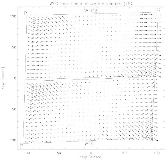
The rhombus shape of the WFC is evident in Figure 7.8. The angle between the X and Y axes is 84.9× for WFC1 and 86.1× for WFC2. The geometric distortion map for WFC1 and WFC2 is illustrated in Figure 10.127, a vector diagram shows the contribution of the non-linear part of a quadratic fit only. The size of the residuals are scaled by a factor of 5 relative to the sky coordinates and could reach the residuals at about 4.1 arcseconds or 82 ACS/WFC pixels. At the center of chip WFC1 the scale in the X direction is 0.0493 arcseconds per pixel, and 0.0486 arcseconds per pixel in the Y direction. In the case of WFC2, the scale is 0.0498 arcseconds per pixel, and 0.0503 arcseconds per pixel in X and Y direction respectively. Between the corner of WFC nearest to the V1 axis and the diagonally opposite corner, the scale increases by 10%. Because of that WFC1 forms a slightly distorted rectangle 201 by 100 arcseconds in size, while WFC2 is 203 by 103 arcseconds. There is a 2.5 arcsecond gap between the two chips.
As it has been shown by Anderson (2007), the linear terms of the ACS/WFC geometric distortion are changing over time and distortion-corrected positions could be off by up to 0.3 pixels from the beginning of ACS observation.
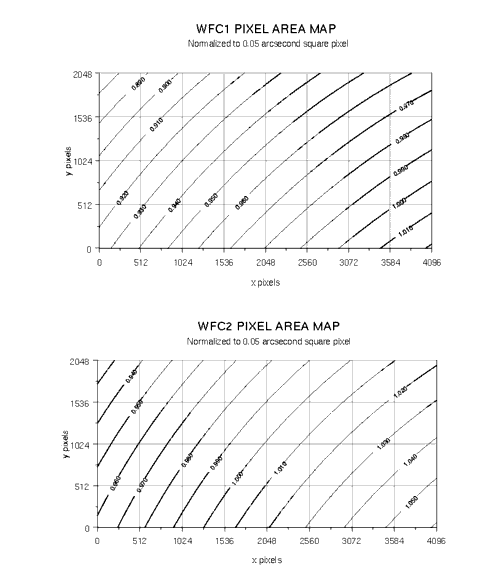
Geometric distortion affects not only the astrometry but the photometry as well, since it induces an apparent variation in surface brightness across the field of view. In order to preserve the photometric accuracy, an additional correction to the photometry is required, by multiplying the ACS/WFC flat-fielded images by the pixel area map. The effective area of each pixel is shown in Figure 10.128 as a contour plot. The range of area is from 0.89 to 1.08 time to the central value.
Figure 10.127: The geometric distortion map for the ACS/WFC, which shows only the non-linear component to the solution. Note that this figure is rotated 180× with respect to the pipeline calibration products, where WFC2 is the lower half of the detector.10.3.2 HRC
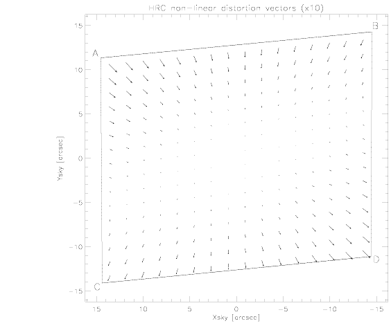
The High Resolution Channel has its edges aligned approximately along the V2 and V3 axes. In this case, the center of the aperture lies on a line passing through the V2V3 origin and making an angle of 22× with the V3 axis. The diagonal of the aperture does not correspond to a radius of the HST field of view. So the distortion has no particular symmetry with respect to the detector axes. The focal plane of HRC is also 25× away from the plane normal to the light path, and because of this the scales along the axes differ by 14%. The full field of view of the HRC is less than 30 arcseconds, therefore the scale variation over the field is much less than for the WFC and it is about 1%. At the center, the X and Y scales are 0.0284 and 0.0248 arcseconds/pixel respectively. The average scales across the middle of the detector are 0.02842 and 0.02485 arcseconds/pixel making the X and Y widths 29.1 and 25.4 arcseconds. The slightly non-square projected aperture shape is evident in Figure 7.8. The angle between the X and Y axes on the sky is 84×.2. The geometric distortion map for HRC is given in Figure 10.129, where the residuals from the non-linearity are scaled by a factor of 10 relative to the sky coordinates and could reach the residuals at about 0.14 arcseconds, or 4.9 ACS/HRC pixels.
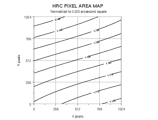
The same as for the WFC, geometric distortion affects not only the astrometry but the photometry as well, and a correction for the pixel area is required to restore the proper total counts of the target. The effective area of each pixel is shown in Figure 10.130 as a contour plot. The maximum deviation from the central value is about 3%.
Figure 10.128: The map of the effective pixel areas of the ACS/WFC chips.10.3.3 SBC
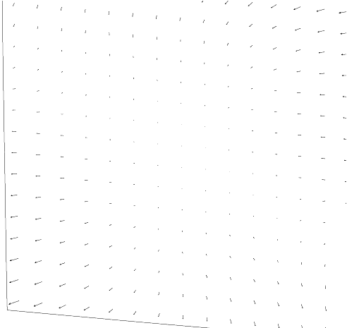
The Solar Blind Channel contains the MAMA detector. It is centered close to the HRC position in the V2V3 plane and has a slightly larger field of view, about 35 by 31 arcseconds. The scales and distortions have now been measured directly. The maximum distortion displacement is about 2 pixels or 0.06 arcseconds. Figure 10.131 shows the distortion map for the SBC detector.
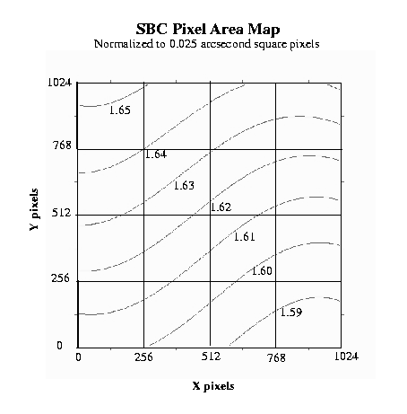
The HRC and SBC both have much smaller areas than the WFC. In the X direction the scale is 0.0338 arcseconds/pixel while in the Y direction it is 0.0301 arcseconds/pixel. Like the HRC, the SBC exhibits a 13% difference between X and Y scales with a variation across the aperture of a little over 2%. The same as for the other cameras, due to geometric distortion, the photometry is also affected by a variation in pixel size across the SBC. The effective area for each pixel is shown in Figure 10.131 as a contour plot. The maximum deviation from the central value is just over 2%. (Gilliland et.al. 2007)
Figure 10.131: The map of the effective pixel areas of the SBC. The areas are normalized to 0.025 arcsecond square pixels.
Figure 10.129: The geometric distortion map for the HRC.Figure 10.130: The map of the effective pixel areas of the HRC.Figure 10.131: The geometric distortion map for the ACS/SBCFigure 10.132: The map of the effective pixel areas of the ACS/SBC
|
Space telescope Science Institute http://www.stsci.edu |