

| HST Phase II Proposal Instructions for Cycle 12 (RPS2) | |||
|
|
8.1 Pointing the Telescope
Acquiring an astronomical target and keeping it fixed in an aperture is the heart of observing with HST. Properly specifying target coordinates and motions is essential, of course, as is finding and acquiring suitable guide stars. Earlier chapters in this document have provided detailed instructions on how to specify coordinates and acquisitions for both fixed and moving targets; see Chapter 3: "Fixed and Generic Targets [Generic _Targets]" and Chapter 4: "Solar System Targets List [Solar_System_Targets]".
8.2 Introduction to Patterns
Only rarely does an observer ask to look at precisely one point on the sky. Instead, small-scale repositionings of the aperture may be made to fully sample a region spatially, or larger-scale movements may be made to mosaic a region of the sky. These movements are known as patterns.
In the past we have defined patterns on an case-by-case basis in a manner that seemed appropriate to each instrument. In rewriting the software that transforms your Phase II program into detailed observations, we realized that these different patterns were sometimes contradictory and incompatible, and that a common basis for describing patterns was needed for the current and future instruments. At the same time, we do not wish to further confuse observers by abandoning terms they may be familiar with, especially if they have continuing programs that could be affected by a change at an arbitrary time.
Here is described this new patterns syntax, which provides both general capabilities and pre-defined "convenience" patterns. A pattern is specified as an exposure-level Special Requirement:
PATTERN <#> [<exposure-list>]
This specifies that each exposure in <exposure-list> (or the current exposure if no <exposure-list> is provided) should be repeated at each point in a pattern of discrete pointing offsets from the target. The <#> should be an integer between 1 and 999 that corresponds to the Pattern_Number of a pattern defined in the Pattern_Data block of the RPS2 file. Details for providing Pattern_Data are given in the next section.
If the exposures in the <exposure-list> contain other expansion constructs (such as Number_of_Iterations > 1 or one of the CR-SPLIT Optional Parameters), the multiple exposures will be taken at each pattern point.
If the <exposure-list> contains coordinated parallels, it must contain the entire parallel sequence (both <parallel-exp-list> and <primary-exp-list> from the PARALLEL WITH Special Requirement; see PARallel <parallel-exp-list> WITH <primary-exp-list>), and only those exposures. All parallel exposures will be taken at each pattern point. Only one PATTERN Special Requirement is allowed within any sequence.
All primary exposures in <exposure-list> must have the same initial pointing: i.e., the same instrument configuration, aperture, target, and POS TARG offsets (if any).
Patterns may be specified for a moving target. In this case the pattern is taken while the target is being tracked and the offsets obtained will be a combination of target motion and motion imposed by the pattern relative to the target.
The following exposure-level Special Requirement is not allowed on an exposure that is part of a pattern:
Patterns are also not allowed with FGS TRANS mode (which specifies a separate scan with the FGS star selectors).
8.3 How to Fill Out the Pattern Parameters Form
The Pattern Parameters Form allows a pattern of pointing offsets to be defined. Patterns are useful for several different purposes: dithering to remove the effects of detector artifacts or to increase spatial resolution, mosaicing to cover a larger area on the sky, or moving away from the target to sample the background.
Patterns are identified by the Pattern_Number field under the Pattern_Data block in the RPS2 file. The value of Pattern_Number must be an integer between 1 and 999. If an exposure anywhere in the proposal uses the PATTERN <#> [<exposure-list>] Special Requirement and <#> matches Pattern_Number, the specified exposures will be repeated at each point of the pattern. It is also possible to specify two nested patterns for an exposure or set of exposures. In this case, instead of taking the exposures at each point of the first pattern, the entire Secondary_Pattern will be executed at each point, creating a two-dimensional matrix of pointing offsets. The parameters for the first pattern appear under the Primary_Pattern label in the RPS2 template. If a second pattern is to be used, a similar Secondary_Pattern label followed by the same set of parameters should be added below the first.

You do not need to specify a Secondary_Pattern unless you wish to, and you may delete it from your template
The Pattern Parameters form looks like this in your RPS2 file:
- Pattern_Data
- Pattern_Number: 11 !unique identifier
- Primary_Pattern:
- Pattern_Type: WFPC2-BOX
- Pattern_Purpose: DITHER
- Number_of_Points: 4
- Point_Spacing: 0.559
- Coordinate_Frame: POS-TARG
- Pattern_Orient: 26.565
- Center_Pattern: ?
Not all fields are required in all cases (see the examples below), and for some patterns both a Primary_Pattern and a Secondary_Pattern must be described. If none of the instrument-specific patterns will work, it is also possible to specify more generic lines and spirals.
8.3.1 Pattern Parameters
The Pattern Parameters Form has the following fields:
Pattern_Number
A unique identifier from 1 to 999.
Pattern_Type
This specifies the type of pattern (generally an instrument-specific name), and, depending on the type, may constrain or completely determine the values of the other parameters. Many pattern types have been defined for the different instruments, as given below. Pattern parameters that are determined by the pattern type, or have default values, need not be entered in the RPS2 file.
Some pattern types are intended for use with a combination of two patterns (Primary_Pattern and Secondary_Pattern). With such pattern types the Secondary_Pattern is mandatory. The Pattern_Type may specify that a parameter of the Secondary_Pattern is constrained or determined by the value of the corresponding parameter of the Primary_Pattern. Whenever two patterns are used, the Pattern_Type of the Secondary_Pattern defaults to the pattern type of the Primary_Pattern, so it is not necessary to enter it under Secondary_Pattern.
A Pattern_Type defined for a particular instrument is legal only if the first primary exposure in the pattern uses that instrument. Generic pattern types are valid with any instrument. Patterns specific to individual instruments are described in the next section; see 8.4 "Convenience Patterns". The following are generic pattern types.
This specifies a linear pattern of offsets, with all other parameters open.
This specifies a spiral pattern, with all other parameters open.
Pattern_Purpose
This is a required text field which describes the scientific purpose of the pattern, but it is treated as a comment to help evaluate the Phase II program. There are four legal values: DITHER, MOSAIC, BACKGROUND, and OTHER:
- DITHER means small-scale motions used to improve spatial resolution and data quality.
- MOSAIC means movement of the aperture to sample different parts of an object or regions of sky.
- BACKGROUND means a movement away from a source to sample the sky background, ordinarily used with infrared instruments.
- If OTHER is used, the reason for the pattern should be provided in the visit or exposure comments. Unless a default is determined via the Pattern_Type, this parameter is required, although you may edit it from the default value to another valid value.
Number_Of_Points
This specifies the number of points in the pattern, from 1 to 50. Unless a default is determined via the Pattern_Type, this parameter is required.
Point_Spacing
This specifies the spacing between adjacent points in a pattern, in arcsec. For parallelogram patterns such as STIS-CCD-BOX, Point_Spacing will specify the length of the segment between the first two pattern points (the spacing between adjacent lines is determined by the Line_Spacing and is not user-specifiable). The value of Point_Spacing ranges from 0 to 1440 arcsec. Unless a default is determined via the Pattern_Type, this parameter is required.
Note: patterns larger than about 130 arcsec (defined by the maximum pointing change between any two points in the pattern) may not be done on a single set of guide stars. For such patterns, unless the entire visit uses gyro guiding (PCS MODE Gyro; see PCS MODE Gyro), the visit-level Special Requirement DROP TO GYRO IF NECESSARY (see DROP TO GYRO IF NECESSARY [NO REACQuisition]) must be specified to allow the farther pattern points to execute under gyro guiding.
Unless PCS MODE Gyro is specified on the visit, all patterns must be contained within a circle of radius 24 arcmin (1440 arcsec), with the first pattern point at the center.
Coordinate_Frame
This field has two legal values, POS-TARG and CELESTIAL. It specifies whether the pattern is being done in the POS TARG (spacecraft) frame or the celestial frame (by specifying offsets from the original target position on the sky). The default is POS-TARG, unless overridden via the Pattern_Type. For patterns with a Pattern_Purpose of DITHER, POS-TARG is the only legal value.
Note: If the NICMOS OFFSET=FOM optional parameter is used, the pattern will be executed by moving the NICMOS Field Offset Mirror, rather than the telescope. In this case, Coordinate_Frame must be set to POS-TARG. All primary exposures in a pattern must use this parameter if any do, and all such exposures must specify the same set of values (if any) for the FOMXPOS and FOMYPOS Optional Parameters.
Pattern_Orient
This field specifies the orientation of the first segment of the pattern with respect to the chosen frame, in degrees. If Coordinate_Frame: POS-TARG, this angle will be measured from the POS TARG +X axis toward the +Y axis. If Coordinate_Frame: CELESTIAL, it will be measured North through East, and will specify the direction of an offset from the target on the sky.
Unless overridden via the Pattern_Type, the default value for Pattern_Orient is 0. This will cause the first pattern segment to be oriented along the POS TARG +X axis if Coordinate_Frame: POS-TARG, and along the North vector on the sky if Coordinate_Frame: CELESTIAL.
Center_Pattern
This indicates whether the pattern should be centered relative to the pointing (hereafter referred to as the "default pointing") that the exposures would have had in the absence of a pattern. For a primary pattern (Primary_Pattern), the default pointing is the target position, unless the POS TARG Special Requirement (see POSition TARGet <X-value>, <Y-value>) is used to shift the target relative to the aperture. For a secondary pattern (Secondary_Pattern), the default pointing is the pointing offset from the target determined by the given pattern point in Primary_Pattern.
Legal values for Center_Pattern are YES and NO. The default is NO, unless overridden via the Pattern_Type. If Center_Pattern: NO, the first pattern point is placed at the default pointing. If Center_Pattern: YES, the first pattern point is offset so that the default pointing is placed at the geometric center of the pattern.
8.4 Convenience Patterns
To minimize confusion, the following patterns use the new syntax but have been constructed to duplicate the earlier pattern forms. Their nomenclature is meant to be obvious, so that "WFPC2-LINE" means the former "LINE" pattern for WFPC2, for example. After each description we show what the RPS2 entries would look like.
A specific entry for a parameter (such as 0.559 for Point_Spacing with WFPC2-BOX) means that value may not be changed and doing so will cause an error. An indicated range (such as 2-10 for Number_of_Points in WFPC2-LINE) means you may select from within that range, and a "?" means any numeric value may be entered.
As noted above, you may also nest patterns, but not all combinations make sense. In the first place, if you use both a Primary_Pattern and a Secondary_Pattern, they should be for the same instrument or at least one should be generic. Do not mix instrument-specific patterns. We have shown below which other patterns may validly be used as a Secondary_Pattern when the indicated one is the Primary_Pattern. When both a Primary_Pattern and a Secondary_Pattern are shown for a given Pattern_Type, both must be used.
8.4.1 WFPC2 Patterns

Note that these new patterns move HST in the opposite direction to the previously-provided WFPC2 patterns. Consult the WFPC2 Instrument Handbook for more information.
To see an illustration of the WFPC2 POS-TARG reference frame, go to 9.4 "WFPC2 Aperture Coordinate System".
Pattern_Type: WFPC2-LINE
This produces a single-line scan, with its default orientation along a 45-degree diagonal with respect to the pixels of the primary camera. The default and strongly recommended single-line dither scan is a two-point scan with a spacing of 0.3535 arcsec between points. This yields an offset of (2.5, 2.5) pixels in the WFC CCDs and (5.5, 5.5) pixels in the PC. This default offset is optimized for resolution enhancement.
If these defaults are not acceptable, the Number_Of_Points, Point_Spacing, and Pattern_Orient parameters may be used to vary the spacing and number of points along the line, and to change the orientation of the line. For example, observers interested only in removing CCD artifacts may prefer to use an integral-pixel offset, as this will simplify the data analysis. An example of an integral-pixel line dither is Point_Spacing: 0.707, which provides offsets of (5,5) pixels in the WFC CCDs and (11,11) pixels in the PC. Please discuss the use of these parameters with your Contact Scientist.
Number_of_Points: 2-10 (default 2)
Point_Spacing: 0.01-3.0 (default 0.3535)
Pattern_Orient: ? (default 45)
Permitted Secondary_Pattern values: LINE, SPIRAL.

Pattern_Type: WFPC2-BOX
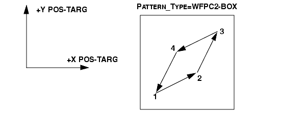
This will produce a four-point parallelogram scan. The four points of the parallelogram will be obtained at the following POS TARG (X,Y) offsets relative to the default aperture position:
(0.0", 0.0") (0.5", 0.25") (0.75", 0.75") (0.25", 0.5")
This default box pattern produces offsets on 0.25 arcsec centers, which represent 2.5 WFC pixels and 5.5 PC pixels. These offsets are optimized for resolution enhancement. If a box-type pattern other than this recommended parallelogram is desired, the POSition TARget special requirement may be used; see POSition TARGet <X-value>, <Y-value>.
The Pattern_Purpose for WFPC2-BOX is DITHER. The Number_Of_Points is 4. The Point_Spacing is 0.559 arcsec. The Coordinate_Frame is POS-TARG. The Pattern_Orient is fixed at 26.565 degrees.
Permitted Secondary_Pattern values: LINE, SPIRAL.
To see an illustration of the WFPC2 POS-TARG reference frame, go to 9.4 "WFPC2 Aperture Coordinate System".
8.4.2 STIS Patterns
To see an illustration of the STIS POS-TARG reference frame, go to 10.9 "STIS Coordinate System".
Pattern_Type: STIS-PERP-TO-SLIT
This is normally used with a spectroscopic slit. It produces a scan along the POS TARG X-axis of the aperture; this is used to map a two-dimensional region of the sky (see Chapter 11 of the STIS Instrument Handbook). The target is moved perpendicular to the slit along the AXIS1 (dispersion) direction.
Pattern_Type: STIS-PERP-TO-SLIT
Permitted Secondary_Pattern values: STIS-ALONG-SLIT, LINE.

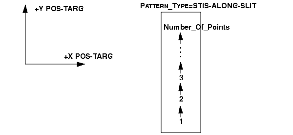
Pattern_Type: STIS-ALONG-SLIT
This is also normally used with a spectroscopic slit. It produces a scan along the POS TARG Y-axis of the aperture; this is used to step a target along the long slit to dither bad pixels or improve spatial resolution (see the STIS Instrument Handbook). The target is moved along the slit in the AXIS2 (cross-dispersion) direction.
Permitted Secondary_Pattern values: none.
To see an illustration of the STIS POS-TARG reference frame, go to 10.9 "STIS Coordinate System".
Pattern_Type: STIS-CCD-BOX
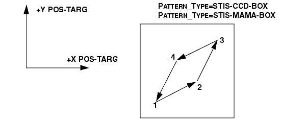
This will produce a four-point parallelogram scan designed for dithering across the CCD pixels. With the default Point_Spacing of 0.567, the four points of the parallelogram will be obtained at the following POS TARG (X,Y) offsets relative to the default aperture position:
(0.0", 0.0") (0.5070", 0.2535") (0.7605", 0.7605") (0.2535", 0.5070")
This default produces a parallelogram pattern (see diagram) with projected offsets from the starting point of 5n integer pixels in each coordinate, so that the above arcsec values correspond to pixel values of (0, 0), (10, 5), (15, 15), and (5, 10). With these integer-pixel offsets, the pattern is optimized to simultaneously compensate for hot pixels and small-scale detector non-uniformities. The pattern can be rescaled (e.g., by a factor of 0.5) to achieve shifts of N+half pixels for resolution enhancement by changing the Point_Spacing.
Point_Spacing: 0.0567-5.67 (default 0.567)
Pattern_Orient: ? (default 26.6)
Permitted Secondary_Pattern values: none.
To see an illustration of the STIS POS-TARG reference frame, go to 10.9 "STIS Coordinate System".
Pattern_Type: STIS-MAMA-BOX
This will produce a four-point parallelogram scan designed for dithering across the MAMA pixels. With the default Point_Spacing of 0.275, the four points of the parallelogram will be obtained at the following POS TARG (X,Y) offsets relative to the default aperture position:
(0.0", 0.0") (0.246", 0.123") (0.369", 0.369") (0.123", 0.246")
This default produces a parallelogram pattern (see diagram) with projected offsets from the starting point of 5n integer pixels in each coordinate, so that the above arcsec values correspond to pixel values of (0, 0), (10, 5), (15, 15), and (5, 10). With these integer-pixel offsets, the pattern is optimized to simultaneously compensate for hot pixels and small-scale detector non-uniformities. The pattern can be rescaled (e.g., by a factor of 0.5) to achieve shifts of N+half pixels for resolution enhancement by changing the Point_Spacing.
Point_Spacing: 0.0275-2.75 (default 0.275)
Pattern_Orient: ? (default 26.6)
Permitted Secondary_Pattern values: none.
Pattern_Type: STIS-SPIRAL-DITH
This produces a spiral dither pattern, starting at the center and moving outward counterclockwise. Note that a STIS-SPIRAL-DITH with four points yields a square pattern, but the optimum pattern for detector dithering to enhance resolution is either STIS-CCD-BOX or STIS-MAMA-BOX.
Pattern_Type: STIS-SPIRAL-DITH
Permitted Secondary_Pattern values: none.
To see an illustration of the STIS POS-TARG reference frame, go to 10.9 "STIS Coordinate System".

8.4.3 ACS Patterns
For general information on ACS patterns, please see the Instrument Science Report titled "ACS Dither and Mosaic Pointing Patterns," to be found at
That document also includes information on modifying these patterns for different uses (e.g., sub-pixel dithering). Also, in response to some frequently asked questions, other useful variations of these dither patterns for dealing with hot pixels and the HRC occulting finger have been defined. They are discussed in:
Pattern_Type: ACS-WFC-DITHER-LINE
General WFC dither line pattern. The default for this pattern shifts the image by 5 pixels in x and 60 in y in order to span the gap between the two WFC detectors.
Pattern_Type: ACS-WFC-DITHER-LINE
Number_Of_Points: 2-9 (default 2)
Point_Spacing: 0.01 - 10.0 (default 3.011)
Pattern_Orient: ? (default 85.28)
Center_Pattern: ? (default NO)

Note: All ACS/WFC users are encouraged to use some form of dithering to allow for correction of hot pixels during data processing. The standard CR-SPLIT approach does not eliminate hot pixels (See Section 12.2.4). Users who would normally have taken that approach in the past are now encouraged to define and use instead the pattern:
Pattern_Type: ACS-WFC-DITHER-LINE
Pattern_Purpose: DITHER
Number_Of_Points: 2
Point_Spacing: 0.146
Coordinate_Frame: POS-TARG
Pattern_Orient: 47.17
Center_Pattern: NO
This pattern will allow simultaneous elimination of hot pixels and cosmic ray hits in post-observation processing. The pattern parameters shift the image by 2 pixels in x and 2 in y along the direction that minimizes the effects of scale variation across the detector.
Pattern_Type: ACS-WFC-DITHER-BOX
This is the default WFC box pattern. It is a 4-point pattern with relative pixel coordinates (0, 0), (5.0, 1.5), (2.5, 4.5), (-2.5, 3.0)-a parallelogram pattern with a combination of integer and sub-pixel shifts, which is relatively compressed in one dimension compared to its WFPC2 and STIS counterparts. This minimizes the effect of scale variation across the detector.
Pattern_Type: ACS-WFC-DITHER-BOX
Center_Pattern: ? (default NO)
Pattern_Type: ACS-WFC-MOSAIC-LINE
General WFC mosaic line pattern. The default shift is in the y direction by 47% of the detector dimension, resulting in a field-of-view that is about 200x300 arcsec. This is a compromise which allows the 2-point WFC mosaic to be performed with one set of guide stars and to cover the interchip gap as well.
Pattern_Type: ACS-WFC-MOSAIC-LINE
Number_Of_Points: 2-9 (default 2)
Point_Spacing: 10.0 - 130.0 (default 96.816)
Pattern_Orient: ? (default 90.0)
Center_Pattern: ? (default YES)
Pattern_Type: ACS-WFC-MOSAIC-BOX
This is a 4-point box pattern for creating a WFC mosaic roughly 400x300 arcseconds. This pattern strikes a compromise with a y-shift that covers the interchip gap (with one set of guide stars) and the maximum x-shift to expand the field of view. So another set of guide stars would be needed only for the x shifts, which are 95% of the detector x dimension (~193 arcsec).
Another useful WFC mosaic box pattern would maximize the field of view (~400x400 arcseconds). For this pattern, both the x and y shifts are ~95% of the detector dimensions, and would require multiple guide stars.
This pattern is also not supported in the ground system, but may be set up by hand using the following POS TARG offsets:
Pattern_Type: ACS-HRC-DITHER-LINE
General HRC dither line pattern. The default for this pattern shifts the image by 5 pixels in x and 5 in y (i.e., on the diagonal) and is useful for removing WFC artifacts.
Pattern_Type: ACS-HRC-DITHER-LINE
Number_Of_Points: 2-9 (default 2)
Point_Spacing: 0.01 - 10.0 (default 0.198)
Pattern_Orient: ? (default 44.28)
Center_Pattern: ? (default NO)
Pattern_Type: ACS-HRC-DITHER-BOX
Same as ACS-WFC-DITHER-BOX, but for the HRC detector.
Pattern_Type: ACS-HRC-DITHER-BOX
Center_Pattern: ? (default NO)
Pattern_Type: ACS-HRC-MOSAIC-LINE
General HRC mosaic line pattern. The default creates a mosaic that shifts the images by 95% of its size in y to roughly double the FOV.
Pattern_Type: ACS-HRC-MOSAIC-LINE
Number_Of_Points: 2-9 (default 2)
Point_Spacing: 10.0 - 130.0 (default 24.130)
Pattern_Orient: ? (default 90.0)
Center_Pattern: ? (default YES)
Pattern_Type: ACS-HRC-MOSAIC-BOX
This is a large 4-point box pattern for creating a mosaic roughly 4 times the HRC field-of-view, or ~52x52 arcsec. The shifts are 95% of the detector dimensions (~973 pixels or ~27.5 arcsec) along both the x and y axes of the detector. Center_Pattern defaults to YES so the target will be at the center of the pattern.
Pattern_Type: ACS-HRC-MOSAIC-BOX
Center_Pattern: ? (default YES)
Pattern_Type: ACS-SBC-DITHER-LINE
General SBC dither line pattern. This pattern shifts the image on the diagonal (10 pixels in x and y).
Pattern_Type: ACS-SBC-DITHER-LINE
Number_Of_Points: 2-9 (default 2)
Point_Spacing: 0.01 - 10.0 (default 0.472)
Pattern_Orient: ? (default 44.40)
Center_Pattern: ? (default NO)
Pattern_Type: ACS-SBC-DITHER-BOX
Same as ACS-WFC-DITHER-BOX, but for the SBC detector.
Pattern_Type: ACS-SBC-DITHER-BOX
Center_Pattern: ? (default NO)
Pattern_Type: ACS-SBC-MOSAIC-LINE
General SBC mosaic line pattern. This pattern shifts the image by 95% in y to roughly double the FOV.
Pattern_Type: ACS-SBC-MOSAIC-LINE
Number_Of_Points: 2-9 (default 2)
Point_Spacing: 10.0 - 130.0 (default 28.801)
Pattern_Orient: ? (default 90.0)
Center_Pattern: ? (default YES)
Pattern_Type: ACS-SBC-MOSAIC-BOX
This is a large 4-point box pattern for creating a mosaic roughly 4 times the SBC field-of-view, or ~64x64 arcsec. The shifts are 95% of the detector dimensions (~973 pixels or ~32 arcsec) along both the x and y axes of the detector.
Pattern_Type: ACS-SBC-MOSAIC-BOX
Center_Pattern: ? (default YES)
8.4.4 NICMOS Patterns
See the NICMOS Instrument Handbook for a full discussion of how and why to use patterns and for complete illustrations of their geometries.
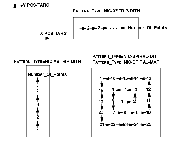
Pattern_Type: NIC-XSTRIP-DITH
This specifies a linear pattern of offsets in the POS TARG +X direction.
Permitted Secondary_Pattern values: NIC-YSTRIP-DITH, NIC-SPIRAL-DITH, NIC-SPIRAL-MAP, NIC-SQUARE-WAVE-DITH, LINE, SPIRAL.
Pattern_Type: NIC-YSTRIP-DITH
This specifies a linear pattern of offsets in the POS TARG +Y direction.
Pattern_Orient: ? (default 90)
Permitted Secondary_Pattern values: NIC-XSTRIP-DITH, NIC-SPIRAL-DITH, NIC-SPIRAL-MAP, NIC-SQUARE-WAVE-DITH, LINE, SPIRAL.
Pattern_Type: NIC-SPIRAL-DITH
This specifies a spiral dither pattern.
Permitted Secondary_Pattern values: NIC-XSTRIP-DITH, NIC-YSTRIP-DITH, NIC-SPIRAL-MAP, NIC-SQUARE-WAVE-DITH, LINE, SPIRAL.
Pattern_Type: NIC-SPIRAL-MAP
This specifies a spiral mosaic pattern.
Permitted Secondary_Pattern values: NIC-XSTRIP-DITH, NIC-YSTRIP-DITH, NIC-SPIRAL-DITH, NIC-SQUARE-WAVE-DITH, LINE, SPIRAL.
Pattern_Type: NIC-SQUARE-WAVE-DITH
This specifies a square-wave pattern with the "amplitude" of the square wave along the POS TARG +Y axis and the main direction of motion along the POS TARG +X axis.
Pattern_Type: NIC-SQUARE-WAVE-DITH
Line_Spacing: Equal to Point_Spacing
Pattern_Orient: ? (default 90)
Permitted Secondary_Pattern values: NIC-XSTRIP-DITH, NIC-YSTRIP-DITH, NIC-SPIRAL-DITH, NIC-SPIRAL-MAP, LINE, SPIRAL.
Pattern_Type: NIC-ONE-CHOP
This requires two pattern definitions. It specifies a repeated "chop" back and forth along the POS TARG +X axis.
Other permitted Secondary_Pattern values: none.
Pattern_Type: NIC-TWO-CHOP
This requires two pattern definitions. It specifies a repeated "chop" along the POS TARG +X axis, similar to NIC-ONE-CHOP, but using four points instead of two.
Line_Spacing: Equal to Point_Spacing
Other permitted Secondary_Pattern values: none.
Pattern_Type: NIC-SPIRAL-DITH-CHOP
This requires two pattern definitions. It specifies a combination of a spiral pattern and a two-point line (the "chop").
Pattern_Type: NIC-SPIRAL-DITH-CHOP
Pattern_Type: NIC-SPIRAL-DITH-CHOP
Pattern_Orient: Equal to <Primary_Pattern value>
Other permitted Secondary_Pattern values: none.
Pattern_Type: NIC-MAP
This specifies a linear mosaic pattern oriented on the sky.
Other permitted Secondary_Pattern values: none.
Pattern_Type: NIC-SKY-ONE-CHOP
This requires two pattern definitions. It specifies a pattern similar to NIC-ONE-CHOP, except that it is oriented on the sky.
Pattern_Type: NIC-SKY-ONE-CHOP
Pattern_Type: NIC-SKY-ONE-CHOP
Other permitted Secondary_Pattern values: none.
Pattern_Type: NIC-SKY-TWO-CHOP
This requires two pattern definitions. It specifies a pattern similar to NIC-TWO-CHOP, except that it is oriented on the sky.
Pattern_Type: NIC-SKY-TWO-CHOP
Pattern_Type: NIC-SKY-TWO-CHOP
Line_Spacing: Equal to Point_Spacing
Other permitted Secondary_Pattern values: none.
Pattern_Type: NIC-SKY-SPIRAL-DITH-CHOP
This requires two pattern definitions. It specifies a combination of a spiral pattern and a two-point line (the "chop"), similar to NIC-SPIRAL-DITH-CHOP except that the pattern is oriented on the sky.
Pattern_Type: NIC-SKY-SPIRAL-DITH-CHOP
Pattern_Type: NIC-SKY-SPIRAL-DITH-CHOP
|
Space Telescope Science Institute http://www.stsci.edu Voice: (410) 338-1082 help@stsci.edu |