|
| Wide Field Camera 3 Instrument Mini-Handbook for Cycle 16 | |||
|
|
2. Instrument Description
2.1 Optical Design
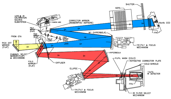
The optical design of WFC3 was driven by the need to provide a large field of view and high sensitivity over a broad wavelength range, excellent spatial resolution, and stable and accurate photometric performance. WFC3 features two independent imaging cameras, the UV/optical channel (UVIS) and the near-infrared channel (IR). Figure 1 shows a schematic diagram of the instrument's optical layout. The UVIS channel uses two butted 4096×2051 thinned, back-illuminated Marconi CCD detectors to support imaging between 200 and 1000 nm. The IR channel uses a 1024×1024 Rockwell HgCdTe detector array, with 1014×1014 pixels useful for imaging, to cover the near-infrared between 900 and 1700 nm. A flat pick-off mirror redirects the on-axis beam coming from the HST Optical Telescope Assembly (OTA) into the WFC3. A channel-select mirror inside WFC3 then diverts the light to the IR channel via a fold mirror, or can be removed from the beam to allow light to enter the UVIS channel. Optical elements in each channel correct for the spherical aberration of the HST primary mirror. Both channels also have internal flat field illumination sources.
The primary characteristics of the two channels are summarized in Table 1.
Table 1: Characteristics of the two WFC3 channels
pixel format
(arcsec)
(arcsec)
Figure 1: Schematic optical layout of the WFC3 instrument. Yellow indicates light from the OTA, which is sent into the camera by the pick-off mirror. The Channel Select Mechanism then either allows light to pass into the UVIS channel (indicated by the blue path), or directs light into the IR channel (red path). Mechanisms and optics in both channels allow for focus and alignment, and correct for the OTA spherical aberration. Filters and grisms are contained in the UVIS SOFA and the IR FSM. The UVIS channel has a mechanical shutter, while the IR channel is shuttered electronically by the detector. Light is detected by either the UVIS CCDs or the IR focal-plane array. A separate subsystem provides flat field illumination for both channels.
2.2 Field of View and Geometric Distortions
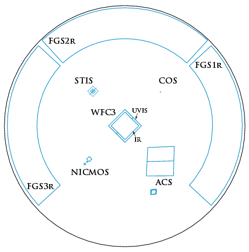
WFC3 will replace WFPC2, Hubble's first large-area camera that included corrections for the spherical aberration of the HST primary mirror. The appearance of the HST focal plane following a fully successful SM4 is shown in Figure 2.
Figure 2: The HST focal-plane layout, showing the instrument complement following a successful SM4. WFC3 will be located on-axis. Outlines of its UVIS and IR channels are shown; they view nearly the same region of the sky, but not simultaneously. The diameter of the outer black circle, projected onto the sky, is about 28 arcminutes.
As is the case for ACS, WFC3 images will be subject to significant geometric distortions. These result primarily from the tilt of the focal plane relative to the optical axis (required for constant focus across the detectors; see Figure 1), which leads to a modest elongation of the field of view in both channels. In the UVIS detector, most of the distortion runs approximately parallel to the diagonal direction of the CCD, while it is parallel to the sides of the detector in the IR channel. As a result, the UVIS field projected onto the sky is shaped like a rhombus, with an acute angle between the x and y axes of the detector of approximately 86 degrees. The IR channel projected onto the sky will be rectangular, with an aspect ratio of about 0.90.
2.3 Spectral Elements
Both WFC3 channels are complemented with a broad selection of spectral elements, chosen on recommendation of the SOC following a Filter Selection Workshop held at STScI on July 14, 1999. The assortment includes broad-, medium-, and narrow-band filters, as well as low-dispersion grisms (one in the UVIS channel, two in the IR channel) for slitless spectroscopy. The broad- and medium-band filters include most of the popular passbands used in extragalactic, stellar, and solar-system astronomy, as well as passbands similar to those already used in other HST instruments for photometric consistency and continuity. The classical UBVRIJH, Str�mgren, and Washington systems are reproduced, along with the filters of the Sloan Digital Sky Survey (SDSS). In addition, several extremely broad-band filters have been included in both channels, for ultra-deep imaging.
There is also a total of 36 different narrow-band passbands in the UVIS channel, consisting of 16 full-field filters and 5 quad filters. (Quad filters are 2×2 mosaics occupying a single filter slot; each one provides four different bandpasses, at the cost of each one covering only about 1/6 of the field of view.) The narrow-band filters provide the capability for high-resolution emission-line imaging in many of the astrophysically important transitions, as well as the methane absorption bands seen in planets, cool stars, and brown dwarfs.
In addition to the broad-band filters, the IR channel includes six narrow-band filters, which likewise sample the most important planetary, stellar, and nebular spectral features in the near-IR.
Finally, broad-band filters with similar wavelength coverages to those of the grism dispersers are available, allowing direct images of spectroscopic targets in the same spectral regions; such images allow accurate identification of the sources as well as providing wavelength calibration.
Unlike ACS or WFPC2, no ramp filters, polarizers, or coronagraphic capabilities are included in either WFC3 channel.
Detailed information about the filters is given in Section 5.2, and Tables 4 and 5 list specifications of the spectral elements of the UVIS and IR channels, respectively, sub-divided by types.
2.4 Detector Read-Out Modes and Dithering
The detectors in both channels offer readouts of subarrays, and the UVIS channel also allows on-chip binning. A variety of dithering schemes will be offered to observers by the Astronomer's Proposal Tool (APT) proposal software, including specially designed "canned" patterns as well as user-defined ones. The post-observation pipeline software will carry out calibration of data taken in all of these configurations, and will offer the option of reconstructing dithered images with a drizzling algorithm. If the dither pattern incorporates non-integer pixel offsets, it effectively improves the sampling of the point-spread function (PSF). The software will also handle mosaicked images according to a set of rules or associations, and will rectify them onto a cartesian pixel coordinate system.
2.5 Comparison with other HST Imaging Instruments
Wavelength Coverage
The WFC3 UVIS channel is similar in design to the Wide Field Channel (WFC) of the ACS. There are, however, a few differences. While ACS/WFC is blind at wavelengths shorter than about 370 nm (i.e., shortward of the B band), WFC3/UVIS has sensitivity extending down to 200 nm. The design trade-offs adopted to achieve this extended UV wavelength coverage (primarily the CCD coating and the use of aluminum coatings for the reflective optics; see Figure 1) lead to a reduced sensitivity of WFC3 at longer optical wavelengths compared to that of ACS/WFC.
The ACS does have UV sensitivity in its High Resolution Channel (HRC). However, compared to ACS/HRC, WFC3/UVIS has a factor of 2 higher throughput at the U band (see Figure 4 below), and a field of view 35 times the area (but with spatial sampling that is 50% coarser). WFC3/UVIS has no sensitivity in the far-UV region below 200 nm. The far-UV is covered by the ACS Solar-Blind Channel (SBC) and, potentially, by the Space Telescope Imaging Spectrograph (STIS) FUV-MAMA, which may be restored to use during SM4.
The WFC3 IR channel also provides nearly a factor of 2 improvement in sensitivity over NICMOS. However, its wavelength coverage is shorter, ending at about 1700 nm (compared with 2500 nm for NICMOS). The WFC3/IR cutoff at 1700 nm greatly reduces the instrument's sensitivity to the thermal background. Unlike NICMOS, the WFC3 IR channel does not have a cryogenic dewar for cooling of instrument components; instead, all optical components of the IR channel are actively cooled by a thermal-control subsystem. Although much simpler than the NICMOS cryocooler, this design allows the IR detector to be cooled only to ~145 K, and thus does not provide adequate suppression of the thermal background at wavelengths longer than ~1700 nm.
Field of View
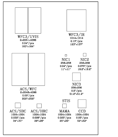
Figure 3 schematically illustrates the fields of view (FOVs), on the same scale, for all of the HST imaging instruments that will be available following a fully successful SM4.
Figure 3: Schematic diagram comparing relative sizes of the fields of view (FOVs) for all HST imaging instruments, following a completely successful SM4. Successive lines of text underneath each FOV give the size in pixels, the pixel scale in arcseconds, and the FOV size in arcseconds. The diagram is schematic, and does not illustrate geometric distortions nor the relative locations in the HST focal plane.
The WFC3 UVIS channel provides about 20% linearly finer pixels than ACS/WFC, obtained at the cost of covering only about 66% of the area of the latter's field of view.
The WFC3 IR channel covers about 6.4 times the area of the NICMOS NIC3 channel, with almost 2 times better spatial sampling, but it lacks the very high spatial samplings offered by the NICMOS/NIC1 and NIC2 channels.
Table 2 presents a comparison of the wavelength coverage, pixel scale, and FOV of WFC3 and of the other HST imaging instruments that will be available following a successful SM4. The table includes the imaging characteristics of STIS, which, however, has been disabled since August 2004.
Table 2: Comparison of wavelength coverage, pixel scales, and fields of view of HST's imaging instruments after a successful SM4.
Detector Performance
The UVIS and IR detectors are anticipated to have excellent performance in terms of read-out noise and dark current.
Table 3 summarizes these properties for the WFC3 flight CCD detector and the flight candidate FPA 129 IR detector, and compares them with these parameters for other HST imaging detectors that will be available following a successful SM4.
See Table 6 for estimates of the limiting magnitudes for WFC3 exposures at UV, optical, and near-IR wavelengths.
Table 3: Characteristics of HST imaging detectors available after SM4. Values for the WFC3 detectors are for the flight CCD and flight candidate IR detector FPA 129. The WFC3/IR dark current includes the instrument thermal background.
Detector
e-/pix/s
System Throughputs and Discovery Efficiencies
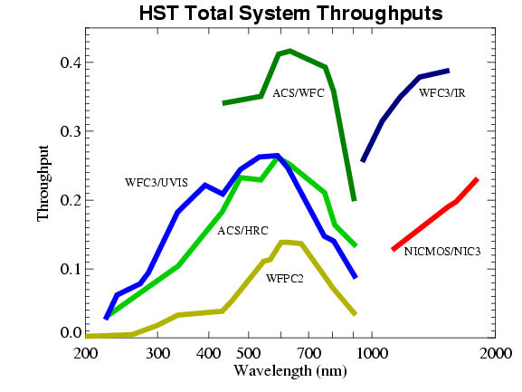
Figure 4 plots the expected system throughputs of the two WFC3 channels as functions of wavelength, compared to those of ACS, NICMOS, and WFPC2. These curves include the throughput of the OTA, all of the optical elements of the instruments themselves, and the sensitivities of the detectors. Throughputs were calculated at the central wavelength (the "pivot wavelength"; see footnote 3 to Table 4 ) of each broad-band filter of each instrument. The WFC3 throughputs are based on the currently selected flight detectors, and are still subject to change at this writing based on further laboratory measurements and the final IR detector choice.
As Figure 4 shows, WFC3 will offer a unique combination of high sensitivity and wide spectral coverage ranging from the UV to the near-IR. WFC3 extends and complements, over a large field of view, the optical performance of ACS/WFC at wavelengths shorter than ~400 nm and longer than 1000 nm. The good degree of functional redundancy with ACS and NICMOS will help ensure that the unique scientific capabilities of HST will remain available until the end of its mission.
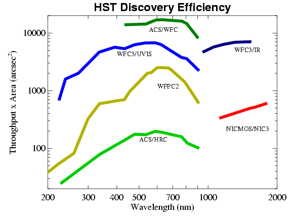
Another quantity that is useful when comparing different instruments, especially in the context of wide-angle surveys, is the "discovery efficiency," defined as system throughput times area of the FOV as projected onto the sky. In Figure 5 we plot the discovery efficiencies of the HST imaging instruments, again vs. wavelength. Note that the y-axis is now logarithmic. This figure dramatically illustrates the enormous gains that WFC3 will offer, compared to the current HST instruments, both in the optical/UV below 400 nm, and in the near-IR.
Figure 4: System throughputs of imaging instruments on HST as functions of wavelength. The plotted quantities are end-to-end throughputs, including filter transmissions, calculated at the pivot wavelength of each broad-band filter of each camera. Throughputs for WFC3 are estimated based on the best information currently available.
Figure 5: Discovery efficiencies of HST imaging instruments, including those expected for WFC3. Discovery efficiency is defined as the system throughput (plotted in Figure 4) multiplied by the area of the field of view. Note that the y-axis is now logarithmic.
|
Space Telescope Science Institute http://www.stsci.edu Voice: (410) 338-1082 help@stsci.edu |