|
| Space Telescope Imaging Spectrograph Instrument Handbook for Cycle 14 | |||||
|
| ||||||
11.3 Patterns and Dithering
A pattern refers to a series of exposures of a single target taken at slightly different telescope pointings, with the same set of guide stars. For STIS, patterns are commonly used to:
- Dither to decrease the effects of small-scale detector nonuniformity, eliminate hot pixels, and/or increase the spatial resolution (the latter requires subpixel stepping) by offsetting the target along a long slit in the spatial direction for spectroscopic observations, or performing a small stepping pattern for imaging or slitless spectroscopic observations (see Section 11.3.5).
- Spectroscopically map out a two-dimensional region of the sky, by stepping the slit across the object of interest.
- Spectroscopically subsample the line-spread function by stepping a fraction of a pixel along the dispersion direction-see Section 12.6.
Predefined patterns were available in Cycles 7 and 8 for STIS, as the RPS2 Optional Parameter
pattern, and for WFPC2, as the Optional Parameterdither-type. In Cycles 9 through 11, patterns were defined and then added to exposures as special requirements. In the APT Orbit Planner, this approach was replaced by the use of Pattern containers. The observer selects a pattern (or constructs a composite pattern) from a list of generic and instrument-specific patterns, and then defines one or more pattern containers which use this selected pattern. The exposures to be dithered are then put into these containers.The predefined STIS patterns have a number of adjustable parameters. All patterns allow the
Point_Spacing, which is given in units of arc-seconds, as well as thePattern_Orient, given in units of degrees, to be adjusted by the observer. SpecifyingCenter_Pattern = YES, will cause the pattern as a whole to be centered at the specified coordinates; otherwise, the given coordinates will apply to the first point in the pattern.A full description of all patterns, including illustrations and a list of all adjustable parameters and default values for each pattern type, are given in the HST
Phase II Proposal Instructions. Additional examples and advice are given in the Dither Handbook at:
http://www.stsci.edu/instruments/wfpc2/Wfpc2_driz/dither_handbook.html.11.3.1 STIS Imaging Patterns
STIS-SPIRAL-DITHcan be used to make a mosaic of images. It performs a spiral dither pattern, starting at the center and moving outward counterclockwise. For this pattern, both theNumber_of_Pointsand thePoint_Spacing(in arc-seconds) must be specified by the observer.
STIS-CCD-BOXandSTIS-MAMA-BOXare parallelograms based on the BOX patterns used with WFPC2 and STIS in Cycle 8 to dither images. The default parameters for these two patterns give offsets in integer numbers of pixels along the X-axis and Y-axis, which can be used, for example, to dither hot pixels. By dividing the default point spacing by 2, one can achieve half-pixel shifts in each coordinate to improve spatial sampling.11.3.2 STIS Spectroscopic Patterns
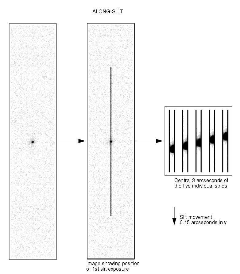
STIS-ALONG-SLIT, which steps the target along the slit, can be used to dither hot pixels (integer pixel steps) or to improve spatial sampling (fractional pixel steps) in spectroscopic images (see Figure 11.7).
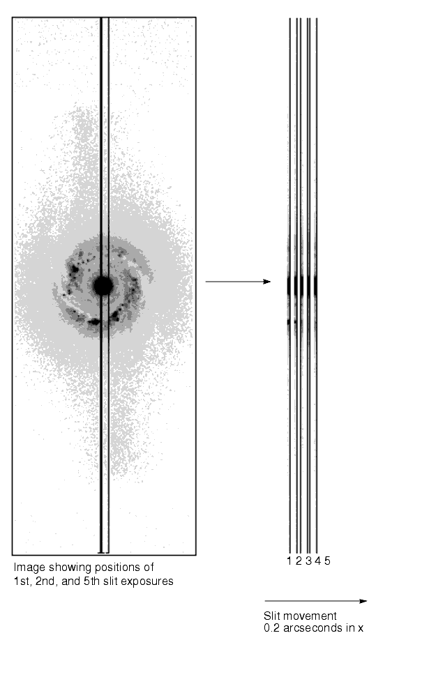
STIS-PERP-TO-SLITcan be used to step the slit across an extended source to map the spectral characteristics of the source (see Figure 11.8). It can also be used to subsample the line-spread function by moving a target by fractions of a pixel.For both of these patterns, the
Point_Spacing(in arc-seconds) and theNumber_of_Pointsmust be specified by the observer.11.3.3 Generic Patterns
Generic patterns, available for all instruments, have been added for flexibility in pattern design. The generic
LINEpattern allows for movement along a line at an arbitrary angle. The genericSPIRALpattern is essentially the same as theSTIS-SPIRAL-DITH.11.3.4 Combining Patterns
A feature that was introduced during Cycle 9 is the ability to combine two patterns. After selecting a pattern and defining the parameters, you can choose to add a secondary pattern. In this case, the secondary pattern is executed at each point in the primary pattern. It can either be centered on the primary points, or can use the primary points as its initial points. For example, instead of just stepping a slit across an extended target at five points with
Figure 11.7: Stepping Target Along Long Slit to dither hot pixels or improve spatial sampling. This example shows the patternSTIS-PERP-TO-SLIT, you can addSTIS-ALONG-SLITwith two points to make a 5x2 grid of observations. IfCenter_Pattern=yesfor both patterns, the grid will be centered on the target position. To check that you have specified a pattern correctly, you can display it using the APT.STIS-ALONG-SLIT, withNumber_of_Points = 5andPoint_Spacing = 0.15(arcsec).
Figure 11.8: Stepping Target Perpendicular to Slit to Map 2-D Region of Sky. This example shows the patternSTIS-PERP-to-SLIT, withNumber_of_Points = 5andPoint_Spacing= 0.2 (arcsec).
11.3.5 Dither Strategies
There is no single observing strategy that is entirely satisfactory in all circumstances for STIS. One must consider cosmic rays, hot pixels (pixels with high, time-variable dark current), and spatial undersampling of the image. One strategy that can be used to minimize the effects of undersampling and to reduce the effects of hot pixels is to dither, that is, to offset the telescope between exposures by either integer or subpixel steps. The best choice for the number and size of the dithers depends on the amount of time available and the goals of the project. In the following we will address a few issues related to dithering:
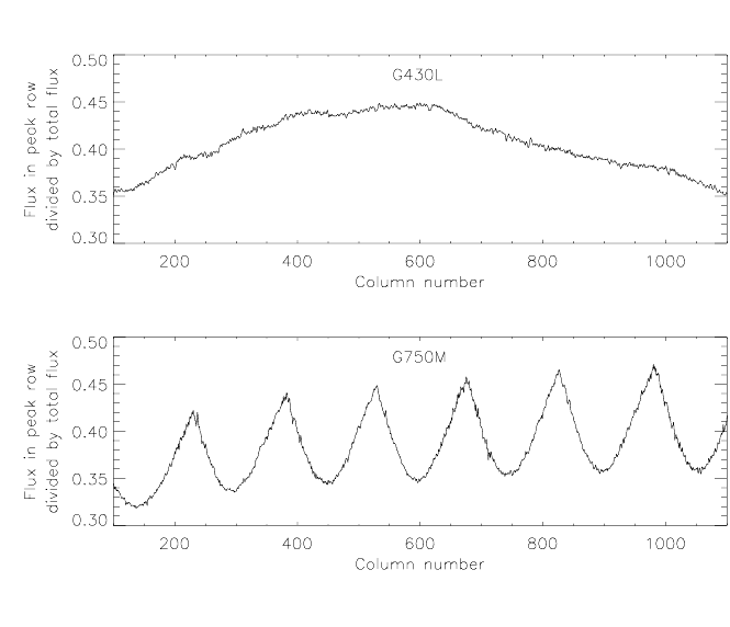
Figure 11.9: Undulations in the flux level of individual rows in rectified spectra of point sources, caused by rectification of spatially undersampled spectral images
- Undersampling of images: Individual images taken with subpixel offsets can be combined to form an image with higher spatial resolution than that of the original images. A single dither from the original pixel position-call it (0,0)-to one offset by half a pixel in both x and y-(0.5,0.5)-will produce a gain in spatial information. On the other hand, very little extra information is gained from obtaining more than four positions. Therefore the recommended number of subpixel dither positions is between 2 and 4. Note that the STIS CCD only marginally undersamples the HST PSF at optical wavelengths, so that the overall gain will not be as substantial as in, e.g., the case of the WF CCDs of WFPC2.
- Undersampling of spectral images: The spatial undersampling of compact sources in spectral images becomes apparent after the images are rectified. Interpolation during the rectification process spreads flux from the local peak row of the spectrum into adjacent rows. The result is undulation of the flux level in the individual spectral rows of the rectified image. If the spectrum is nearly horizontal on the detector (which is the case for gratings
G140L,G230LB,G230MB,G430L, andG750L), the resulting undulation pattern is broad and irregular. On the other hand, if the spectrum has an appreciable tilt across the detector (as for gratingsG140M,G230M,G230L,G430M, andG750M; see e.g., STIS Instrument Science Report1998-19), the undulation is quasi-periodic. Two representative cases are shown in Figure 11.9, which displays the flux in the peak row in the rectified image normalized by the total flux for stellar observations taken withG430LandG750M. Note that this effect is inconsequential in most cases: if the source is unresolved, several rows of the spectrum will be extracted to make a single spectrum, eliminating the effect; if the source is sufficiently extended to be well sampled, the undulations will not occur. A problematic situation is encountered when row-by-row spectral analyses are needed of an extended component which is affected by the undulations produced by a compact component (e.g., near the center of a galaxy containing an active nucleus). For example, kinematic measurements of spatially extended emission or absorption lines can be affected in cases where a compact continuum component produces a baseline that fluctuates rapidly across the spectral lines of interest. The remedy is to perform spatial dithering by a non-integer number of pixels along the slit, (e.g., N+0.5 pixels; see below under "Dithering Spectroscopic Observations"), then combine the dithered images before rectification.
- Hot Pixels: There are three ways to deal with hot pixels: (1) correct using "superdarks" constructed from darks taken on the day of the observation (these can be created using STSDAS task daydark); (2) use a task such as warmpix in STSDAS to filter out the known hot pixels. Hot pixels are flagged in the data quality array during dark subtraction and propagate through to the output images; (3) dither by an integer number of pixels. Note that the integer dither strategy would ideally consist of six images, i.e., two
CR-SPLITimages at each of three different dither positions. The reason is that in addition to hot pixels, low or cold pixels can be present and simple strategies selecting the minimum of two pixel values can fail. However, even four images (two each at two dither positions) will greatly aid in eliminating hot-pixel artifacts.- The MAMA detectors show few hot pixels and they appear to evolve slowly. Thus they are usually not an issue. Nevertheless, dithering is an easy way to avoid them, and there is no read noise or cosmic-ray removal penalty for doing so.
- Cosmic Rays: Although dithering naturally provides many images (or spectra) of the same field it is better to take several exposures at each individual pointing in order to remove cosmic rays. In principle, it should be possible to remove cosmic rays using dithered data with only one exposure per position. Indeed, publicly released software is available for this task (the dither package within IRAF/STSDAS, see below). However, this software is only applicable to imaging mode observations, and one should realize that calibrating dithered data with only one exposure per position will require significantly more work (and CPU cycles) than processing data with two or more exposures per position. Hence we generally recommend obtaining two or more exposures (i.e.,
CR-SPLIT) at each position in the dithered sequence, especially for spectroscopy mode observations (see also Section 7.2.3).- Dithering Spectroscopic Observations: In case of spectroscopic observations, extra care should be taken in choosing the optimum dither strategy, which depends on the spatial extent of the extractions and the nature of the science target. However, beware that dithering spectroscopic observations will only be useful if your exposure times are long enough, otherwise your spectra will become severely read-noise limited (see page Section 7.2.3).
- Spectra of Point Sources: 1-D first-order spectra of point sources are usually extracted over 7 spatial pixels for CCD, 11 spatial pixels for MAMA (e.g., during STIS pipeline processing). Hence, the effect of hot pixels is exacerbated compared to the case of imaging observations. If sufficient time is available to perform dithers, the best practice is to dither the target by an offset large enough to avoid having the same hot pixels fall in the individual extracted spectrograms. This means that you should move the spectrum by more than 0.55 arcsec (for an 11 pixel extraction) along the slit between dither positions. Unfortunately, that will make cosmic ray removal more difficult unless you get two or more spectra at each individual pointing (using CR-SPLIT). Ideally, taking CR-SPLIT=3 observations at multiple dither positions allows the most robust cosmic ray rejection and hot pixel removal in post-observation data processing for spectra.
- Spectra of Extended Sources: For extended sources, one should consider the spatial size of the extractions to be made during post-observation analysis before deciding on a dither strategy. To enable a proper rejection of hot pixels within the extractions, the telescope move between dithers should be larger than the spatial size of the extractions made. In case the region of interest is at or near a sharp peak in the surface brightness distribution, one should consider dithering by a non-integer number of pixels to deal with the undulation issue due to undersampling (cf. above).
- Accuracy of Dithering: During the Hubble Deep Field campaign, nearly all dithers were placed to within 10 milliarcsec (mas) (during ± 1.3 arcsec offsets and returns separated by multiple days), although in a few cases the dither was off by more than 25 mas, and on one occasion (out of 107 reacquisitions) the telescope locked on a secondary FGS peak causing the pointing to be off by approximately 1 arcsec, as well as a field rotation of about 4 arcminutes. The software which was developed for the Hubble Deep Field is able to reconstruct images even for these nonoptimal dithers, still gaining in resolution over nondithered data. This software is presently available in STSDAS (the dither package) and is based on the variable-pixel linear-reconstruction technique developed by Fruchter and Hook (known as drizzling). It has been used successfully on STIS imaging data.
- Flat-Field Accuracy: For the MAMAs, the accuracy of flat fielding has not been extensively tested, especially for the imaging modes. Dithering on scales of several pixels can help to smooth out pixel-to-pixel variations in detector sensitivity. For this purpose it is best to use dither steps that are not integral multiples of half a pixel (the intrinsic high-resolution format of the MAMAs); integral pixel steps should be used instead.
The simplest way to schedule dithers with STIS is to use the patterns
STIS-CCD-BOXorSTIS-MAMA-BOX(four-point parallelogram dithers, centering on fractional pixels to gain spatial resolution) or, for spectroscopic observations that use a long slit, the patternSTIS-ALONG-SLIT(for linear dithers in theAXIS2direction, with user-specified offsets). An alternate approach is to usePOS TARG.Note that large dithers will incur small errors due to the camera geometric distortion which increases toward the CCD corners and alters the image scale by about 1% at the corners. For instance, a 20 pixel offset at the field center will suffer a 0.2 pixel error at the CCD corners. Large dithers may also occasionally require a different set of guide stars for each pointing, thus greatly reducing the expected pointing accuracy (accuracy of only ~1 arcsec due to limits to the accuracy of the Guide Star Catalogue).
For related articles on dither strategies, see the following papers (all available through the STScI web pages): "
A Package for the Reduction of Dithered Undersampled Images," by Fruchter et al., in the 1997 HST Calibration Workshop Proceedings, theWFPC2 Instrument Science Report 98-04, and "A Method for the Linear Reconstruction of Undersampled Images" by Fruchter & Hook (2002, PASP, 114, 144), and the Dither Handbook of Koekemoer et al., which can be found at:
http://www.stsci.edu/instruments/wfpc2/Wfpc2_driz/dither_handbook.html.
|
|
|||||
|
Space Telescope Science Institute http://www.stsci.edu Voice: (410) 338-1082 help@stsci.edu |