|
| Cosmic Origins Spectrograph Instrument Handbook for Cycle 17 | ||||
|
|
7.6 FUV Dispersed-Light Acquisitions
COS includes flight software that can find and center a source in the selected aperture by working with the dispersed spectrum. This can be done with either the FUV or NUV detector. A dispersed-light acquisition has the advantage of analyzing the same image that will then be integrated to form the science spectrum. However, there are some disadvantages to acquiring in dispersed light:
- Instead of obtaining only a single image that is then analyzed to determine a centroid (as in
ACQ/IMAGEmode), in dispersed light the telescope is moved a number of times to create a spiral search pattern on the sky, and the accumulated counts are then analyzed. At each dwell point a separate exposure is needed, and then HST must be moved a small amount. Those exposures and motions are each fairly short, but they add up, resulting in a fairly slow acquisition.- Mostly because of lower S/N, dispersed-light acquisitions achieve pointing precision of about 0.1 arcsec, which is not as good as
ACQ/IMAGE.- In dispersed light, airglow (or geocoronal) emission features fill the aperture and can produce high count rates that make source detection difficult. This problem is most severe in the FUV and is averted by ignoring portions of the detector illuminated by airglow features.
7.6.1 FUV dispersed-light acquisition summary
Airglow lines and sub-arrays
Nearly all the strong airglow lines are in the FUV (see a list of lines and strengths in Chap5xx). Of these, Lyman-
is by far the most important. To avoid the airglow lines, the dispersed-light acquisition process reads discrete sub-arrays on the XDL detector. In addition, segment B, which records the shortest wavelengths, gets very little light when grating G140L is used, and therefore only segment A is used for an acquisition with G140L.
Steps in an acquisition
There are four steps needed to center a target with a dispersed-light acquisition:
- The Pt-Ne comparison lamp is turned on so that the position of its image can be found. The known offset between the calibration and science spectra then indicates the location of the aperture on the detector.
- A spiral search is then carried out, in a spiral pattern, making a square with 2, 3, 4, or 5 points on a side. At each scan point the telescope stops and an integration is taken. The resultant n × n image is then analyzed and the telescope is moved to center the object.
- A peak-up in the cross dispersion direction is performed to improve the centering (
PEAKXD).- A peak-up in the along-dispersion direction is done as well (
PEAKD).The last two steps are optional and should be done in the order indicated (
PEAKXDthenPEAKD). Also, any one step may be done more than once (such as doing a 3 × 3 spiral search followed by a 2 × 2 one to improve the centering). As a result, there is a huge number of possible ways to acquire a target and improve its centering. Here we will concentrate on some specific scenarios that achieve good results in a reasonable time.7.6.2 Mode=ACQ: The spiral target search
The initial target search is done with the ACQ command for the
COS/FUVconfiguration. You will need to specify:
- The aperture to use, either
PSAorBOA.- The spectrum element (i.e., which grating) to be used and the wavelength setting. This should be the same as the grating and wavelength to be used for the science spectrum that follows.
- The
SCAN-SIZE, which is2,3,4, or5, corresponding to spiral patterns of 2 × 2, 3 × 3, etc.- The exposure time per dwell point.
Large
SCAN-SIZEvalues should only be used in cases where the target coordinates are mediocre, which should occur only rarely. A 3 × 3 pattern should be adequate in virtually all cases. Note that the evenSCAN-SIZEvalues (2 or 4) entail some additional overhead time because there is an additional movement of the telescope needed to displace the aperture by half ofSTEP-SIZEin both x and y (the coordinate system at the aperture). This is so the overall pattern remains centered on the initial pointing.The
STEP-SIZEparameter determines the spacing, in arcsec, between dwell points in the pattern. It may be set at any value from 0.2 to 2.0 arcsec, but we strongly recommend using the default value of 1.767 arcsec. This default value has been chosen so that no part of the sky is missed, given the 2.5 arcsec diameter aperture (2.5/2 = 1.767).
Finding the source
Once the integrations have all been done, the flight software determines what point in the array to return to, and there are three options. The default, and recommended, option is
CENTER=FLUX-WT. This algorithm uses a flux-weighted centroiding procedure to determine the center of the light and has been shown in simulations to be effective in locating a source. The algorithm contains a check that removes dwell points from the calculation if the number of counts at that point is below a certain percentage of the maximum counts seen in any one dwell point. That threshold is set at 10% and is not selectable by the observer.A variation on
FLUX-WTis to useCENTER=FLUX-WT-FLR. In this case a floor is subtracted from all the array's data points before the centroid is computed, and that floor is taken as the minimum number of counts seen in any one dwell point.FLUX-WT-FLRhas the advantage of getting rid of background counts, but leaves one point in the array with zero. This can cause computational problems, and, as a result,FLUX-WT-FLRmay not be used withSCAN-SIZE=2.The last option for centering is to use
CENTER=BRIGHTESTwhich simply centers the dwell point with the most counts. This is straightforward but not as accurate as the centroiding methods.The methodology used to locate the spectrum is to collapse it in the x direction, to make use of the relatively few counts that have been detected. It is for this reason that
Figure 7.1: Example of a 3 × 3 spiral search pattern.ACQ/SEARCHcenters the spectrum well in the cross-dispersion direction, but not as well along the dispersion.
This example was executed with the default STEP-SIZE of 1.767 arcsec. The blue circles represent the nine positions of the aperture, each 2.5 arcsec in diameter, and the numbers show the sequence of steps. The large outer circle in red has a radius of 3 arcsec. Thus an initial pointing that was good to 1 arcsec (1) would result in a successful acquisition with a 3 × 3 pattern 99.5% of the time.
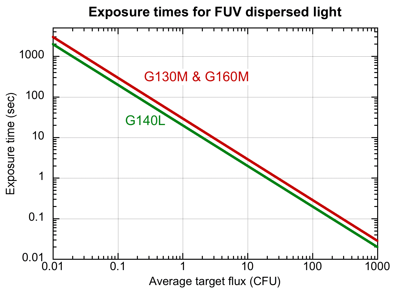
Exposure times
Figure 7.2 allows you to estimate the exposure time needed for an FUV acquisition in dispersed light. The COS acquisition ETC should be used to get actual values, of course.
Figure 7.2: Exposure times needed for FUV dispersed-light acquisitions.
The calculations have been made for a flat source spectrum and are based on achieving S/N = 40.
Quality of centering after ACQ/SEARCH
This is being written before we have on-orbit experience with COS and so we rely on computational simulations. Those simulations, using realistic estimates of source brightness, coordinate accuracy, and noise levels, predict that the
ACQ/SEARCHstage, by itself, together withCENTER=FLUX-WTshould lead to a source being centered to within 0.2 arcsec in the along-dispersion direction and 0.1 arcsec in the cross-dispersion direction. However, statistical effects play a role, and the worst-case errors were 1.3 arcsec. IfCENTER=BRIGHTESTis used instead, simulations show that the centering can often be off by 0.4 arcsec or more.FLUX-WT-FLRalso produced good results, but not as good asFLUX-WT.7.6.3 PEAKXD: Peaking up in the cross-dispersion direction
As noted, in most cases an
ACQ/SEARCHby itself will center a source well in the cross-dispersion direction, generally well enough for most purposes. However, an additional command,ACQ/PEAKXD, exists to enable that centering to be improved.
ACQ/PEAKXDworks very much likeACQmode except that no movement of the telescope occurs. As with anACQ, withPEAKXDyou specify the aperture to use (PSAorBOA, the same as for your science exposure, in general); the grating and central wavelength, and the exposure time. You can optionally choose to just use one of the segments, A or B, but use of the default is recommended. The default uses both segments except that only segment A is used with G140L set at 1105 Ĺ.Simulations show that use of
PEAKXDshould end up centering a source to within 0.03 to 0.04 arcsec in almost all cases.7.6.4 PEAKD: Peaking up in the along-dispersion direction
A COS spectrum as imaged onto the FUV detector has some aberrations, but is still basically a line. This makes the determination of the spectrum's center in the cross-dispersion direction straightforward, but centering the source in the aperture in the along-dispersion direction using the dispersed spectrum is not as easy. At the same time, as we noted above, the centering in the along-dispersion direction is more important for the quality of the spectrum because it helps assure the wavelength zero point.
The
ACQ/PEAKDcommand works very much likeACQexcept that instead of a spiral, a linear motion of HST is made to integrate the spectrum. As withACQ, the centroid is then computed. The number of steps may be chosen as 3, 5, 7, or 9, with 3 being the default. TheSTEP-SIZEcan be 0.01 to 2.0 arcsec, and there is no default value. The value ofSTEP-SIZEchosen clearly depends on the precision of centering desired. If the initialACQis good to 0.3 arcsec (see above), then a 9-pointPEAKDwithSTEP-SIZE=0.07should find the object reliably and center it to a fraction of thatSTEP-SIZE.As with
ACQ, there are three options for the centering algorithm,CENTER=FLUX-WT,=FLUX-WT-FLR, and=BRIGHTEST, and they work in the same way as described above. We recommend that you specifyCENTER=DEFAULT, which useFLUX-WTifNUM-POS=3, but usesFLUX-WT-FLRifNUMPOS=5,7or9.Each execution of
ACQ/PEAKDneeds about 2 minutes total, even for fairy faint sources (1 CFU) with G130M.
|
Space Telescope Science Institute http://www.stsci.edu Voice: (410) 338-1082 help@stsci.edu |