

The complete wavelength range for each grating, as well as the wavelength coverage per tilt for the scanned grating modes, is shown in a table and graphically. The exact wavelengths at the ends of the ranges for the MAMA detectors will depend on the MAMA monthly offsetting. This procedure shifts the spectrogram so that it falls on slightly different parts of the MAMA detectors from month to month in order to minimize charge depletion in the microchannel plates and can cause the loss of ±30 pixels from either end of the spectrogram in dispersion (AXIS1) and ±80 pixels in cross-dispersion (AXIS2). Spectral format plots of the STIS grating and central wavelength settings are available from the STIS web page under "Gratings." For the echelles, the monthly offsetting will project the extreme orders of formats off of the detector in some months. The wavelength ranges for the echelles given in the chapter therefore include only the orders which are guaranteed to project onto the detector. Whenever possible, choose a central wavelength that keeps your features of interest away from the extremes of the wavelength ranges.
Wavelengths in this handbook and in STIS data products are always measured in vacuum conditions.
This chapter contains plots and tables of sensitivities and throughputs for each grating mode. Section 6.2 in the Exposure-Time Calculation chapter explains how to use these sensitivities to calculate expected count rates from your source.
The total system1 spectroscopic point-source sensitivity,  , has the unit:
counts sec-1 pix -1 per incident erg cm-2 sec-1 Å-1 for the MAMA and electrons sec-1 pix-1 per incident erg cm-2 sec-1 Å-1 for the CCD,
= a pixel in the dispersion direction.

|
Note that the spectroscopic point-source sensitivity does not include slit losses. |
The spectroscopic diffuse source sensitivity,  , has the units
counts sec-1 pix-1 pixs-1 per incident erg sec-1 cm-2 Å-1 arcsec-2 for the MAMA and electrons sec-1 pix-1 pixs-1 per incident erg sec-1 cm-2 Å-1 arcsec-2 for the CCD,
 and
and  are related through the relation:

Here, we have assumed that the diffuse source has a uniform brightness over the area of interest and that the spectrum can be approximated as a continuum source. The throughput is defined as the end-to-end effective area divided by the geometric area of a filled, unobstructed 2.4 meter aperture (see Chapter 6).
Tables of sensitivities and throughputs are given for a point source placed in the center of the largest clear aperture for each detector. (Sensitivities and throughputs for a point source placed high on the CCD detector in the long-slit "E1" pseudo-apertures will be measured from calibration data taken in Cycles 10 and 11; see Section 7.2.7). The sensitivity plots give values for point and diffuse sources. In the plots in this chapter we show the diffuse source sensitivity for a 0.1 arcsec wide slit. For an extended continuum source,  scales directly with slit width, as above.
For the echelles, the sensitivities given were derived from fits of a smooth curve as a function of wavelength to the measured sensitivities at the central wavelength of each order (i.e., they do not include the effect of the echelle ripple). The STIS Exposure-Time Calculator (see Chapter 6) will properly take the echelle ripple into account and should be used for more detailed S/N analysis.
Small but significant changes in the STIS sensitivity have been revealed by continuous observations of the same standard stars in the 52 x 2 slit. These changes are discussed in detail in the sections entitled Section 7.1.4, and Section 7.3.3, and the mean variations in sensitivity with time for some first order MAMA configurations are illustrated in Figure 7.13:.
The sensitivities and throughputs listed in this chapter have not been corrected for the time dependent changes discussed above, but rather are the values as originally measured in 1997-1998. In many cases they are therefore higher than the current sensitivities by a few to several percent. Likewise, the STIS Exposure Time Calculator (ETC) does not currently take the time dependence of the sensitivity into account. Until this is implemented, the ETC results will thus have a comparable uncertainty.
For each grating mode, a plot is provided to help you estimate the signal-to-noise (S/N) for a class of sources and a range of exposure times, corresponding to a fiducial taken at wavelengths near the peak of the responses. The fiducial wavelength is indicated in the ordinate label of each plot. To estimate signal-to-noise at alternate wavelengths, you can scale your source flux or magnitude by the relative sensitivities (or throughputs) at the wavelength of interest and at the fiducial. The point source plots show S/N as a function of F and of V+STMAG() for a range of exposure times; the diffuse source plots show I and V+ STMAG() per arcsec2 for a range of exposure times. Using STMAG units is natural in this plot given that a particular STMAG value corresponds to a flux distribution with a constant value of F. In producing these plots we assumed an average sky background (as described in Chapter 6) and the appropriate values for read noise and dark current for each detector. Note the following:
52X0.2 slit for the first-order modes and the use of the 0.2X0.2 slit for the echelle modes.
CR-SPLIT=2 and CCDGAIN=1.
(or I) exceeds the indicated value, the observation would exceed the observing limits (recall that the observing limits are at slightly higher count rates than the screening limits given in Table 13.44). For diffuse sources we indicate only the local rate limit, since the global limit is dependent on the source extent. If no line is seen on the plot, it indicates the limit is higher than the range of fluxes plotted.
In situations requiring more detailed calculations (non-stellar spectra, extended sources, other sky background levels, etc.), the STIS ETC, available from the STIS web site under "Software Tools," should be used instead.
Follow these steps to use the S/N plots:
.
derived from the table.
on the horizontal axis. Read off the S/N for the desired exposure time, or vice-versa. Alternatively use F directly on the horizontal axis.
CR-SPLIT exposures, one should use the sub-exposure time when consulting the plot, and then multiply the resulting S/N by  , where N is the number of sub-exposures to be averaged. Recall that these plots assume
 CR-SPLIT=2 for CCD observations.
We now give a sample S/N calculation using these plots. Consider a V=18 star of spectral class B0 V, for which we want to derive the S/N for a 100 sec CR-SPLIT exposure in G430L with the CCD. We look up the B0 V spectral class and interpolate in the table between 4000 Å (STMAG = -1.20) and 4500 Å (STMAG= -0.78) to obtain STMAG ~-1 at 4300 Å. We thus have V+STMAG= 17. We look at Figure 13.12: and find this value on the horizontal axis. We locate exposure time 100 and find S/N ~10. This exposure is well below the saturation lines in the plot, so saturation is not a concern.
In the grating information section, the plate scale (units: arcseconds/pixel) is given in the table for each grating. The values used have been obtained from imaging observations and have been approximated at 0.05 arcseconds/pixel for the CCD modes, and 0.025 arcseconds/pixel for the G140L and G230L MAMA modes (see Section 14.6). The other MAMA spectroscopy modes operate at a lower magnification, yielding a cross-dispersion plate scale of 0.029 arcseconds/pixel. Anamorphic magnification by the gratings further modifies the plate scales in the dispersion direction, particularly for the echelle modes. The relevant scales in both directions have been used in the generation of each grating's diffuse source sensitivity and signal-to-noise plots.
The exact level of anamorphic magnification is a function of grating and central wavelength. More detailed information on the CCD modes can be found in ISR 98-23 "Plate Scales, Anamorphic Magnification & Dispersion: CCD Modes" by C. Bowers and S. Baum.
For each supported slit (aperture) we provide a table giving the name of the slit, length (in the spatial direction) and width (in the dispersion direction) of the slit as well as a table and plot of the relative throughput of the slit (with respect to a large clear aperture) as a function of wavelength. Recall, that the point source sensitivities that we have derived assume zero slit losses. Your calculations of exposure times must account for light losses for the desired slit. Aperture throughputs measured in orbit are given in Instrument Science Reports 98-20 and 98-25. These measurements were used to revise pre-launch models of the aperture throughputs as a function of wavelength, and these revised models were then used to calculate the aperture throughput information given in this chapter and in the aperture throughputs (apt) reference file. Currently, aperture throughputs at the CTE E1 positions (see Section 7.2.7) in the 52" long slits are assumed to be the same as the throughputs at the standard positions in the same aperture. Calibration data taken in Cycles 10 and 11 will be used to directly measure the aperture throughputs at the E1 positions, and resulting revisions will be made available in a STIS Instrument Science Report and on the "STIS Apertures" web page.
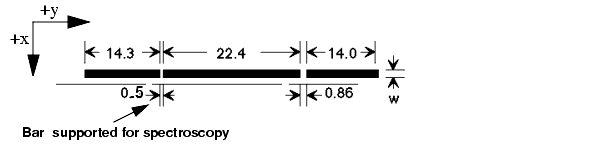
Each STIS long slit has two fiducial bars, located 11.2 arc-seconds above and below the slit center (see Figure 13.1 below). They have several purposes. First, the bars provide structural integrity for the long slits. Second, the image of the bars obtained in wavecal (and target acquisition) images is used by the calibration software to locate the projection of the aperture on the detector in post-observation data processing. Lastly, the bars can be used to occult a source thereby providing a coronagraphic spectroscopic capability for STIS. We continue to support use of the 0.5 arcsecond long bar on the 52X0.2 slit (the 52X0.2F1 aperture) for such observations. We refer you to Section 12.9 for more information about performing coronagraphic spectroscopy, and Section 13.7.3 for some caveats.
For each grating mode information about the cross dispersion (spatial) profiles is provided as follows:
We show plots of predicted line spread functions (LSFs) for CCD and MAMA spectroscopic modes ( Section 13.6), as a function of wavelength and slit width. These plots are based on models of the PSFs at the aperture plane and detector PSFs that have been updated and verified using on-orbit data.
Tables
for the spectral type and wavelength region of your target observation (e.g. G0 V @ 4300Å).
derived from Step 1.
on the horizontal axis and read off the S/N for the desired exposure time (or read off the exposure time for the desired S/N).
|
Space Telescope Science Institute http://www.stsci.edu Voice: (410) 338-1082 help@stsci.edu |