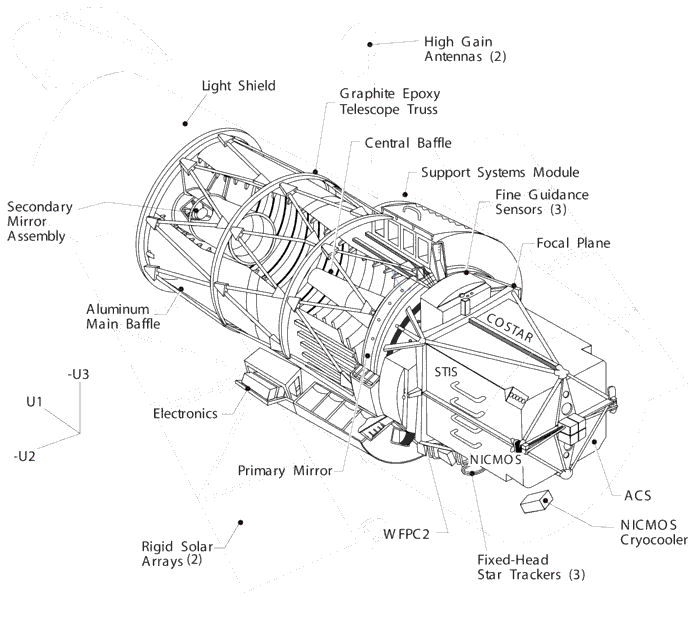


The design and layout of HST are shown schematically in Figure 2.1. The telescope receives electrical power from two solar arrays, which are turned (and the spacecraft rolled about its optical axis) so that the panels face the incident sunlight. Nickel-hydrogen batteries power the telescope during orbital night. Two high-gain antennae provide communications with the ground via the Tracking and Data Relay Satellite System (TDRSS). Power, control, and communications functions are carried out by the Support Systems Module (SSM) that encircles the primary mirror.
The SIs are mounted in bays behind the primary mirror. The WFPC2 occupies one of the radial bays with an attached 45-degree pickoff mirror that allows it to receive the on-axis beam. There are three Fine Guidance Sensors (FGSs) which occupy the other radial bays and receive light 10-14 arcminutes off-axis. Since at most two FGSs are required to guide the telescope, it is possible to conduct astrometric observations with the third FGS. The remaining SIs are mounted in the axial bays and receive images several arcminutes off-axis.
When referring to the HST and its focal plane, we use a coordinate system that is fixed to the telescope and consists of three orthogonal axes: U1, U2 and U3. As shown in Figure 2.1, U1 lies along the optical axis, U2 is parallel to the solar-array rotation axis, and U3 is perpendicular to the solar-array axis. (Note: Some HST documentation uses the alternative V1, V2, V3 coordinate system for which V1=U1, V2=-U2 and V3=-U3.)
Figure 2.1: The Hubble Space Telescope. Major components are labelled, and definitions of the U1,U2,U3 spacecraft axes are indicated.

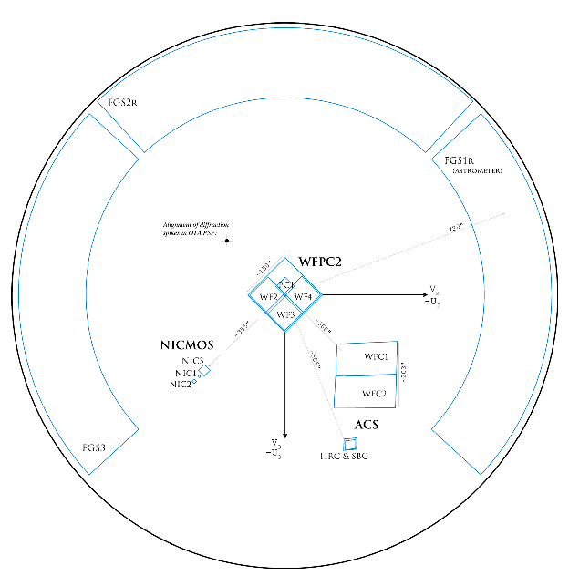
Figure 2.2 shows the layout of the instrument entrance apertures in the telescope focal plane as projected onto the sky.
Table 2.1 lists the rough effective locations of the SI apertures in the U2,U3 coordinate system. Precise values depend on subtleties in aperture definitions and operational modes. The HST Instrument Handbooks (see Section 1.2) should be consulted for more accurate details of each instrument's aperture locations and characteristics.
| Instrument |
Aperture |
U2 (arcsec) |
U3 (arcsec) |
|---|---|---|---|
| ACS |
WFC HRC SBC |
-259 -206 -205 |
-239 -472 -467 |
| FGS |
FGS1R |
-722 |
8 |
| NICMOS |
NIC1 NIC2 NIC31 |
294 321 269 |
-288 -314 -256 |
| WFPC2 |
PC WF2 WF3 WF4 |
-2 51 0 -55 |
30 6 -49 6 |
| 1Position shown is for NIC1 and NIC2 compromise PAM location. |


|
Space Telescope Science Institute http://www.stsci.edu Voice: (410) 338-1082 help@stsci.edu |