|
Note that these new patterns move HST in the opposite direction to the previously-provided WFPC2 patterns. Consult the |


To minimize confusion, the following patterns use the new syntax but have been constructed to duplicate the earlier pattern forms. Their nomenclature is meant to be obvious, so that "WFPC2-LINE" means the former "LINE" pattern for WFPC2, for example. After each description we show what the information would look like.
A specific entry for a parameter (such as 0.559 for Point_Spacing with WFPC2-BOX) means that value may not be changed and doing so will cause an error. An indicated range (such as 2-10 for Number_of_Points in WFPC2-LINE) means you may select from within that range, and a "?" means any numeric value may be entered.
As noted above, you may also nest patterns, but not all combinations make sense. In the first place, if you use both a Primary_Pattern and a Sub-Pattern (or Secondary_Pattern in the Text Proposal File), they should be for the same instrument or at least one should be generic. Do not mix instrument-specific patterns. We have shown below which other patterns may validly be used as a Sub-Pattern when the indicated one is the Primary_Pattern. When both a Primary_Pattern and a Sub-Pattern are shown for a given Pattern_Type, both must be used.

|
Note that these new patterns move HST in the opposite direction to the previously-provided WFPC2 patterns. Consult the |
To see an illustration of the WFPC2 POS-TARG reference frame, go to Section 9.4 .
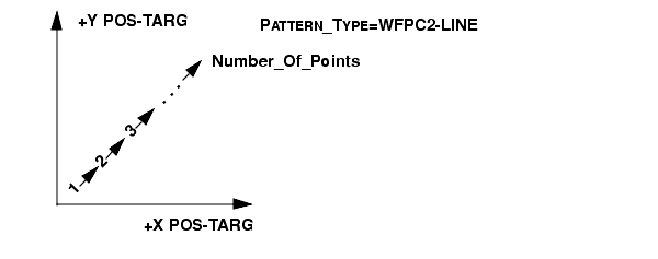
This produces a single-line scan, with its default orientation along a 45-degree diagonal with respect to the pixels of the primary camera. The default and strongly recommended single-line dither scan is a two-point scan with a spacing of 0.3535 arcsec between points. This yields an offset of (2.5, 2.5) pixels in the WFC CCDs and (5.5, 5.5) pixels in the PC. This default offset is optimized for resolution enhancement.
If these defaults are not acceptable, the Number_Of_Points, Point_Spacing, and Pattern_Orient parameters may be used to vary the spacing and number of points along the line, and to change the orientation of the line. For example, observers interested only in removing CCD artifacts may prefer to use an integral-pixel offset, as this will simplify the data analysis. An example of an integral-pixel line dither is Point_Spacing: 0.707, which provides offsets of (5,5) pixels in the WFC CCDs and (11,11) pixels in the PC. Please discuss the use of these parameters with your Contact Scientist (or contact help@stsci.edu).
Patter	n_Type	: WFPC2-LINE

Pattern_Purpose:	DITHER

Number_of_Points:	2-10 (default 2)

Point_Spacing:	0.01-3.0 (default 0.3535)

Coordinate_Frame:	POS-TARG

Pattern_Orient:	? (default 45)

Center_Pattern:	?
Permitted Sub-Pattern (Secondary_Pattern) values: LINE, SPIRAL.
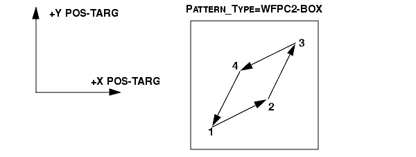
This will produce a four-point parallelogram scan. The four points of the parallelogram will be obtained at the following POS TARG (X,Y) offsets relative to the default aperture position:
(0.0", 0.0") (0.5", 0.25") (0.75", 0.75") (0.25", 0.5")
This default box pattern produces offsets on 0.25 arcsec centers, which represent 2.5 WFC pixels and 5.5 PC pixels. These offsets are optimized for resolution enhancement. If a box-type pattern other than this recommended parallelogram is desired, the POSition TARget special requirement may be used; see POSition TARGet <X-value>,<Y-value>.
The Pattern_Purpose for WFPC2-BOX is DITHER. The Number_Of_Points is 4. The Point_Spacing is 0.559 arcsec. The Coordinate_Frame is POS-TARG. The Pattern_Orient is fixed at 26.565 degrees.
Pattern_Type:	WFPC2-BOX

Pattern_Purpose:	DITHER

Number_of_Points:	4

Point_Spacing:	0.559

Line_Spacing:	0.559 (may not be changed)

Angle_Between_Sides:	143.13 (may not be changed)

Coordinate_Frame:	POS-TARG

Pattern_Orient:	26.56505

Center_Pattern:	?
Permitted Sub-Pattern (Secondary_Pattern) values: LINE, SPIRAL.
To see an illustration of the WFPC2 POS-TARG reference frame, go to Section 9.4 .
For general information on ACS pointing, and a library of carefully designed dither and mosaic pointing patterns (ready for use in a Phase II proposal), see the following Web page:
http://www.stsci.edu/hst/acs/proposing/dither
In addition to the default patterns provided below, many non-default variations are included in the pattern library (e.g., for hot pixel rejection, sub-pixel dithering, etc.) and parameters are updated using the latest distortion solution. Helpful diagrams and descriptions are provided along with Phase II pattern parameters.
General WFC dither line pattern. The default for this pattern shifts the image by 5 pixels in x and 60 in y in order to span the gap between the two WFC detectors.
Pattern_Type: ACS-WFC-DITHER-LINE

Pattern_Purpose: DITHER

Number_Of_Points: 2-9 (default 2)

Point_Spacing: 0.01 - 10.0 (default 3.011)

Coordinate_Frame: POS-TARG

Pattern_Orient: ? (default 85.28)

Center_Pattern: ? (default NO)
Permitted Sub_Pattern (Secondary_Pattern) values: any other ACS/WFC patterns, LINE, BOX, SPIRAL
|
Note: All ACS/WFC (and HRC) users are encouraged to use some form of dithering to allow for correction of hot pixels during data processing. The standard CR-SPLIT approach does not eliminate hot pixels (See Section 11.2.4). Users who would normally have taken that approach in the past are now encouraged to define and use instead the pattern: |
This is the default WFC box pattern. It is a 4-point pattern with relative pixel coordinates (0, 0), (5.0, 1.5), (2.5, 4.5), (-2.5, 3.0)-a parallelogram pattern with a combination of integer and sub-pixel shifts, which is relatively compressed in one dimension compared to its WFPC2 and STIS counterparts. This minimizes the effect of scale variation across the detector.
Pattern_Type: ACS-WFC-DITHER-BOX

Pattern_Purpose: DITHER

Number_Of_Points: 4

Point_Spacing: 0.01 - 10.0 (default 0.265)

Line_Spacing: 0.01 - 10.0 (default 0.187)

Angle_Between_Sides: 0 - 360 (default 69.05)

Coordinate_Frame: POS-TARG

Pattern_Orient: 0 - 360 (default 20.67)

Center_Pattern: ? (default NO)
Permitted Sub_Pattern (Secondary_Pattern) values: any other ACS/WFC patterns, LINE, BOX, SPIRAL
General WFC mosaic line pattern. The default shift is in the y direction by 47% of the detector dimension, resulting in a field-of-view that is about 200x300 arcsec. This is a compromise which allows the 2-point WFC mosaic to be performed with one set of guide stars and to cover the inter chip gap as well.
Pattern_Type: ACS-WFC-MOSAIC-LINE

Pattern_Purpose: MOSAIC

Number_Of_Points: 2-9 (default 2)

Point_Spacing: 10.0 - 130.0 (default 96.816)

Coordinate_Frame: POS-TARG

Pattern_Orient: ? (default 90.0)

Center_Pattern: ? (default YES)
Permitted Sub_Pattern (Secondary_Pattern) values: any other ACS/WFC patterns, LINE, BOX, SPIRAL
This is a 4-point box pattern for creating a WFC mosaic roughly 400x300 arc seconds. This pattern strikes a compromise with a y-shift that covers the inter chip gap (with one set of guide stars) and the maximum x-shift to expand the field of view. So another set of guide stars would be needed only for the x shifts, which are 95% of the detector x dimension (~193 arcsec).
Another useful WFC mosaic box pattern would maximize the field of view (~400x400 arcseconds). For this pattern, both the x and y shifts are ~95% of the detector dimensions, and would require multiple guide stars.
This pattern is also not supported in the ground system, but may be set up by hand using the following POS TARG offsets:
General HRC dither line pattern. The default for this pattern shifts the image by 5 pixels in x and 5 in y (i.e., on the diagonal) and is useful for removing WFC artifacts.
Pattern_Type: ACS-HRC-DITHER-LINE

Pattern_Purpose: DITHER

Number_Of_Points: 2-9 (default 2)

Point_Spacing: 0.01 - 10.0 (default 0.198)

Coordinate_Frame: POS-TARG

Pattern_Orient: ? (default 44.28)

Center_Pattern: ? (default NO)
Permitted Sub_Pattern (Secondary_Pattern) values: any other ACS/HRC patterns, LINE, BOX, SPIRAL
Same as ACS-WFC-DITHER-BOX, but for the HRC detector.
Pattern_Type: ACS-HRC-DITHER-BOX

Pattern_Purpose: DITHER

Number_Of_Points: 4

Point_Spacing: 0.01 - 10.0 (default 0.150)

Line_Spacing: 0.01 - 10.0 0.(default 0.098)

Angle_Between_Sides: 0 - 360 (default 63.50)

Coordinate_Frame: POS-TARG

Pattern_Orient: 0 - 360 (default 19.89)

Center_Pattern: ? (default NO)
Permitted Sub_Pattern (Secondary_Pattern) values: any other ACS/HRC patterns, LINE, BOX, SPIRAL
General HRC mosaic line pattern. The default creates a mosaic that shifts the images by 95% of its size in y to roughly double the FOV.
Pattern_Type: ACS-HRC-MOSAIC-LINE

Pattern_Purpose: MOSAIC

Number_Of_Points: 2-9 (default 2)

Point_Spacing: 10.0 - 130.0 (default 24.130)

Coordinate_Frame: POS-TARG

Pattern_Orient: ? (default 90.0)

Center_Pattern: ? (default YES)
Permitted Sub_Pattern (Secondary_Pattern) values: any other ACS/HRC patterns, LINE, BOX, SPIRAL
This is a large 4-point box pattern for creating a mosaic roughly 4 times the HRC field-of-view, or ~52x52 arcsec. The shifts are 95% of the detector dimensions (~973 pixels or ~27.5 arcsec) along both the x and y axes of the detector. Center_Pattern defaults to YES so the target will be at the center of the pattern.
Pattern_Type: ACS-HRC-MOSAIC-BOX

Pattern_Purpose: MOSAIC

Number_Of_Points: 4

Point_Spacing: 0.01 - 10.0 (default 24.130)

Line_Spacing: 0.01 - 10.0 (default 27.670)

Angle_Between_Sides: 0 -360 (default 95.85)

Coordinate_Frame: POS-TARG

Pattern_Orient: 0 - 360 (default 90.0)

Center_Pattern: ? (default YES)
Permitted Sub_Pattern (Secondary_Pattern) values: any other ACS/HRC patterns, LINE, BOX, SPIRAL
General SBC dither line pattern. This pattern shifts the image on the diagonal (10 pixels in x and y).
Pattern_Type: ACS-SBC-DITHER-LINE

Pattern_Purpose: DITHER

Number_Of_Points: 2-9 (default 2)

Point_Spacing: 0.01 - 10.0 (default 0.472)

Coordinate_Frame: POS-TARG

Pattern_Orient: ? (default 44.40)

Center_Pattern: ? (default NO)
Permitted Sub_Pattern (Secondary_Pattern) values: any other ACS/SBC patterns, LINE, BOX, SPIRAL
Same as ACS-WFC-DITHER-BOX, but for the SBC detector.
Pattern_Type: ACS-SBC-DITHER-BOX

Pattern_Purpose: DITHER

Number_Of_Points: 4

Point_Spacing: 0.01 - 10.0 (default 0.179)

Line_Spacing: 0.01 - 10.0 (default 0.116)

Angle_Between_Sides: 0 - 360 (default 63.65)

Coordinate_Frame: POS-TARG

Pattern_Orient: 0 - 360 (default 20.02)

Center_Pattern: ? (default NO)
Permitted Sub_Pattern (Secondary_Pattern) values: any other ACS/SBC patterns, LINE, BOX, SPIRAL
General SBC mosaic line pattern. This pattern shifts the image by 95% in y to roughly double the FOV.
Pattern_Type: ACS-SBC-MOSAIC-LINE

Pattern_Purpose: MOSAIC

Number_Of_Points: 2-9 (default 2)

Point_Spacing: 10.0 - 130.0 (default 28.801)

Coordinate_Frame: POS-TARG

Pattern_Orient: ? (default 90.0)

Center_Pattern: ? (default YES)
Permitted Sub_Pattern (Secondary_Pattern) values: any other ACS/SBC patterns, LINE, BOX, SPIRAL
This is a large 4-point box pattern for creating a mosaic roughly 4 times the SBC field-of-view, or ~64x64 arcsec. The shifts are 95% of the detector dimensions (~973 pixels or ~32 arcsec) along both the x and y axes of the detector.
Pattern_Type: ACS-SBC-MOSAIC-BOX

Pattern_Purpose: MOSAIC

Number_Of_Points: 4

Point_Spacing: 10.0 - 130.0 (default 28.801)

Line_Spacing: 10.0 - 130.0 (default 32.957)

Angle_Between_Sides: 0 - 360 (default 95.76)

Coordinate_Frame: POS-TARG

Pattern_Orient: 0 - 360 (default 90.0)

Center_Pattern: ? (default YES)
Permitted Sub_Pattern (Secondary_Pattern) values: any other ACS/SBC patterns, LINE, BOX, SPIRAL
See the NICMOS Instrument Handbook for a full discussion of how and why to use patterns and for complete illustrations of their geometries.
This specifies a linear pattern of offsets in the POS TARG +X direction.
Pattern_Type:	NIC-XSTRIP-DITH

Pattern_Purpose:	DITHER

Number_of_Points:	?

Point_Spacing:	?

Coordinate_Frame:	POS-TARG

Pattern_Orient:	? (default 0)

Center_Pattern:	?
Permitted Sub-Pattern (Secondary_Pattern) values: NIC-YSTRIP-DITH, NIC-SPIRAL-DITH, NIC-SPIRAL-MAP, NIC-SQUARE-WAVE-DITH, LINE, SPIRAL.
This specifies a linear pattern of offsets in the POS TARG +Y direction.
Pattern_Type:	NIC-YSTRIP-DITH

Pattern_Purpose:	DITHER

Number_of_Points:	?

Point_Spacing:	?

Coordinate_Frame:	POS-TARG

Pattern_Orient:	? (default 90)

Center_Pattern:	?
Permitted Sub-Pattern (Secondary_Pattern) values: NIC-XSTRIP-DITH, NIC-SPIRAL-DITH, NIC-SPIRAL-MAP, NIC-SQUARE-WAVE-DITH, LINE, SPIRAL.
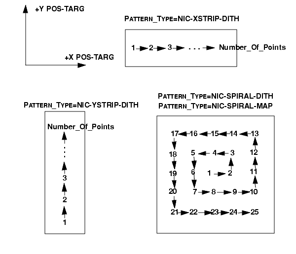
This specifies a spiral dither pattern.
Pattern_Type:	NIC-SPIRAL-DITH

Pattern_Purpose:	DITHER

Number_of_Points:	?

Point_Spacing:	?

Coordinate_Frame:	POS-TARG

Pattern_Orient:	? (default 0)

Center_Pattern:	?
Permitted Sub-Pattern (Secondary_Pattern) values: NIC-XSTRIP-DITH, NIC-YSTRIP-DITH, NIC-SPIRAL-MAP, NIC-SQUARE-WAVE-DITH, LINE, SPIRAL.
This specifies a spiral mosaic pattern.
Pattern_Type:	NIC-SPIRAL-MAP

Pattern_Purpose:	MOSAIC

Number_of_Points:	?

Point_Spacing:	?

Coordinate_Frame:	CELESTIAL

Pattern_Orient:	?

Center_Pattern:	?
Permitted Sub-Pattern (Secondary_Pattern) values: NIC-XSTRIP-DITH, NIC-YSTRIP-DITH, NIC-SPIRAL-DITH, NIC-SQUARE-WAVE-DITH, LINE, SPIRAL.
This specifies a square-wave pattern with the "amplitude" of the square wave along the POS TARG +Y axis and the main direction of motion along the POS TARG +X axis.
Pattern_Type:	NIC-SQUARE-WAVE-DITH

Pattern_Purpose:	DITHER

Number_of_Points:	?

Point_Spacing:	?

Line_Spacing:	Equal to Point_Spacing (may not be
changed)

Angle_Between_Sides:	270 (may not be changed)

Coordinate_Frame:	POS-TARG

Pattern_Orient:	? (default 90)

Center_Pattern:	?
Permitted Sub-Pattern (Secondary_Pattern) values: NIC-XSTRIP-DITH, NIC-YSTRIP-DITH, NIC-SPIRAL-DITH, NIC-SPIRAL-MAP, LINE, SPIRAL.
This requires two pattern definitions. It specifies a repeated "chop" back and forth along the POS TARG +X axis.
Pattern_Type:	NIC-ONE-CHOP

Pattern_Purpose:	BACKGROUND

Number_of_Points:	?

Point_Spacing:	0

Coordinate_Frame:	POS-TARG

Pattern_Orient:	0

Center_Pattern:	NO
Pattern_Type:	NIC-ONE-CHOP

Pattern_Purpose:	BACKGROUND

Number_of_Points:	2

Point_Spacing:	?

Coordinate_Frame:	POS-TARG

Pattern_Orient:	? (default 0)

Center_Pattern:	NO
Other permitted Sub-Pattern (Secondary_Pattern) values: none.
This requires two pattern definitions. It specifies a repeated "chop" along the POS TARG +X axis, similar to NIC-ONE-CHOP, but using four points instead of two.
Primary pattern:

Pattern_Type:	NIC-TWO-CHOP

Pattern_Purpose:	BACKGROUND

Number_of_Points:	?

Point_Spacing:	0

Coordinate_Frame:	POS-TARG

Pattern_Orient:	0

Center_Pattern:	NO
Pattern_Type:	NIC-TWO-CHOP

Pattern_Purpose:	BACKGROUND

Number_of_Points:	4

Point_Spacing:	?

Line_Spacing:	Equal to Point_Spacing (may not be
changed)

Angle_Between_Sides:	0 (may not be changed)

Coordinate_Frame:	POS-TARG

Pattern_Orient:	? (default 0)

Center_Pattern:	NO
Other permitted Sub-Pattern (Secondary_Pattern) values: none.
This requires two pattern definitions. It specifies a combination of a line pattern and a two-point line at right angles (the "chop").
Pattern_Type:	NIC-XSTRIP-DITH-CHOP

Pattern_Purpose:	DITHER

Number_of_Points:	?

Point_Spacing:	?

Coordinate_Frame:	POS-TARG

Pattern_Orient:	? (default 0)

Center_Pattern:	? (default NO)
Pattern_Type:	NIC-XSTRIP-DITH-CHOP

Pattern_Purpose:	BACKGROUND

Number_of_Points:	2

Point_Spacing:	?

Coordinate_Frame:	POS-TARG

Pattern_Orient:	? (default 90)

Center_Pattern:	NO
Other permitted Sub-Pattern (Secondary_Pattern) values: none.
This requires two pattern definitions. It specifies a combination of a line pattern and a two-point line at right angles (the "chop").
Pattern_Type:	NIC-YSTRIP-DITH-CHOP

Pattern_Purpose:	DITHER

Number_of_Points:	?

Point_Spacing:	?

Coordinate_Frame:	POS-TARG

Pattern_Orient:	? (default 90)

Center_Pattern:	? (default NO)
Pattern_Type:	NIC-YSTRIP-DITH-CHOP

Pattern_Purpose:	BACKGROUND

Number_of_Points:	2

Point_Spacing:	?

Coordinate_Frame:	POS-TARG

Pattern_Orient:	? (default 0)

Center_Pattern:	NO
Other permitted Sub-Pattern (Secondary_Pattern) values: none.
This requires two pattern definitions. It specifies a combination of a spiral pattern and a two-point line (the "chop").
Pattern_Type:	NIC-SPIRAL-DITH-CHOP

Pattern_Purpose:	DITHER

Number_of_Points:	?

Point_Spacing:	?

Coordinate_Frame:	POS-TARG

Pattern_Orient:	? (default 0)

Center_Pattern:	?
Pattern_Type:	NIC-SPIRAL-DITH-CHOP

Pattern_Purpose:	BACKGROUND

Number_of_Points:	2

Point_Spacing:	?

Coordinate_Frame:	POS-TARG

Pattern_Orient: Equal to <Primary_Pattern value>

Center_Pattern:	NO
Other permitted Sub-Pattern (Secondary_Pattern) values: none.
This specifies a linear mosaic pattern oriented on the sky.
Pattern_Type:	NIC-MAP

Pattern_Purpose:	MOSAIC

Number_of_Points:	?

Point_Spacing:	?

Coordinate_Frame:	CELESTIAL

Pattern_Orient:	?

Center_Pattern:	?
Pattern_Type:	NIC-MAP

Pattern_Purpose:	MOSAIC

Number_of_Points:	?

Point_Spacing:	?

Coordinate_Frame:	CELESTIAL

Pattern_Orient:	?

Center_Pattern:	?
Other permitted Sub-Pattern (Secondary_Pattern) values: none.
This requires two pattern definitions. It specifies a pattern similar to NIC-ONE-CHOP, except that it is oriented on the sky.
Pattern_Type:	NIC-SKY-ONE-CHOP

Pattern_Purpose:	BACKGROUND

Number_of_Points:	?

Point_Spacing:	0

Coordinate_Frame:	CELESTIAL

Pattern_Orient:	0

Center_Pattern:	NO
Pattern_Type:	NIC-SKY-ONE-CHOP

Pattern_Purpose:	BACKGROUND

Number_of_Points:	2

Point_Spacing:	?

Coordinate_Frame:	CELESTIAL

Pattern_Orient:	?

Center_Pattern:	NO
Other permitted Sub-Pattern (Secondary_Pattern) values: none.
This requires two pattern definitions. It specifies a pattern similar to NIC-TWO-CHOP, except that it is oriented on the sky.
Pattern_Type:	NIC-SKY-TWO-CHOP

Pattern_Purpose:	BACKGROUND

Number_of_Points:	?

Point_Spacing:	0

Coordinate_Frame:	CELESTIAL

Pattern_Orient:	0

Center_Pattern:	NO
Pattern_Type:	NIC-SKY-TWO-CHOP

Pattern_Purpose:	BACKGROUND

Number_of_Points:	4

Point_Spacing:	?

Line_Spacing:	Equal to Point_Spacing (may not be
changed)

Angle_Between_Sides	0 (may not be changed)

Coordinate_Frame:	CELESTIAL

Pattern_Orient:	?

Center_Pattern:	NO
Other permitted Sub-Pattern (Secondary_Pattern) values: none.
This requires two pattern definitions. It specifies a combination of a spiral pattern and a two-point line (the "chop"), similar to NIC-SPIRAL-DITH-CHOP except that the pattern is oriented on the sky.
Pattern_Type:	NIC-SKY-SPIRAL-DITH-CHOP

Pattern_Purpose:	DITHER

Number_of_Points:	?

Point_Spacing:	?

Coordinate_Frame:	POS-TARG

Pattern_Orient:	? (default 0)

Center_Pattern:	? (default NO)
Pattern_Type:	NIC-SKY-SPIRAL-DITH-CHOP

Pattern_Purpose:	BACKGROUND

Number_of_Points:	2

Point_Spacing:	?

Coordinate_Frame:	CELESTIAL

Pattern_Orient:	(default 0)

Center_Pattern:	NO
Other permitted Sub-Pattern (Secondary_Pattern) values: none.


|
Space Telescope Science Institute http://www.stsci.edu Voice: (410) 338-1082 help@stsci.edu |